- ページ 5
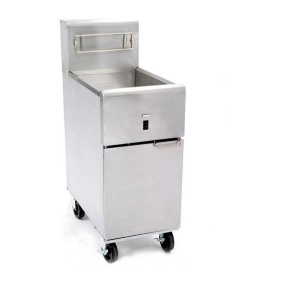
フライヤー Dean SR114EのPDF インストレーション&オペレーションマニュアルをオンラインで閲覧またはダウンロードできます。Dean SR114E 12 ページ。 Super runner series electric fryers
Dean SR114E にも: インストレーション&オペレーションマニュアル (12 ページ), サービス&パーツマニュアル (20 ページ)

CLEARANCE AND VENTILATION
This fryer must be installed with a 6-inch (150-mm) clearance at both sides and back when installed adjacent to
combustible construction. No clearance is required when installed adjacent to non-combustible construction. A
minimum of 24-inches (600-mm) clearance should be provided at the front of the fryer.
INSTALLATION
For units equipped with legs: Lift the unit and move it into its final position. Do not drag or push the fryer into position.
Doing so may damage the legs. Level the unit front to back and side to side. If the fryer is not level, the unit will not
function efficiently.
A. Adjust leg height with an adjustable or 1-1/16-inch (27-mm) open-end wrench by turning the hexagon-shaped foot
on the bottom of the leg. NOTE: The foot is for minor leg height adjustment only. Do not adjust outward more
than ¾-inch (19-mm).
B. When leveling the unit, the leg body should be held firmly to keep the leg from bending or rotating while turning the
foot to the required height.
For units equipped with casters: Roll the unit into its final position and lock the front casters.
When the fryer is leveled in its final position, install the restraints provided with the unit to limit its movement so
that it does not depend on or transmit stress to the electrical conduit or connection. Install the restraints in
accordance with the provided instructions (see illustration below). If the restraints are disconnected for service or
other reasons, they must be reconnected before the fryer is used.
1.3 Power Requirements
MODEL
14 kW
14 kW
14 kW
14 kW
14 kW
The electrical power supply for this appliance MUST be the same as indicated on the rating and serial
This appliance MUST be connected to the voltage and phase specified on the rating and serial
All wiring connections for this appliance MUST be made in accordance with the wiring diagrams
furnished with the equipment. Wiring diagrams are located inside the fryer door.
SUPER RUNNER SERIES ELECTRIC FRYERS
CHAPTER 1: INSTALLATION INSTRUCTIONS
Use copper wire ONLY suitable for at least 194F (90C)
VOLTAGE
PHASE
208
Single
208
3
240
Single
240
3
230/400
3
number plate located on the inside of the fryer door.
number plate located inside the fryer door.
MINIMUM WIRE
WIRE
SIZE
SERVICE
AWG
3
4
3
8
3
4
3
8
4
6
DANGER
DANGER
DANGER
1-2
AMPS
(per leg)
mm
(5.83)
68
(4.11)
39
(5.19)
59
(3.26)
34
(4.11)
21
