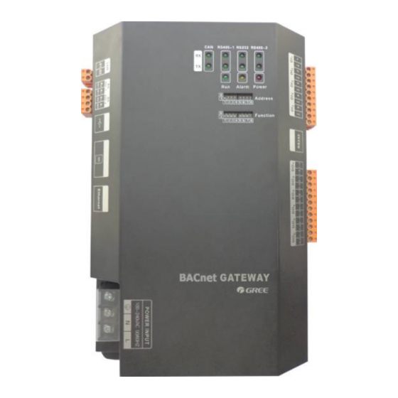
RX
CAN
TX
CAN
RX
RS485-1
TX
RS485-1
RX
RS232
TX
RS232
RX
RS485-2
TX
RS485-2
Power
Run
Alarm
1.3 DI/DO
So far, this gateway supports 5 DIs (digital input) and 5 Dos (digital output), DO6 is reserved.
DI1...DI5
Digital input 0/1 digital signal (binary system), apply to active input.
DI 1: in CAN2 network, fire alarm signal, connect "1" to the power of 12V, input fire alarm
signal "1" in DI 1 port, then BACnet gateway will give out control, all units stop operation
immediately; disconnect "1" or connect to "0", input signal "0" in DI 1 port, resume operation of
all ODUs.
In CAN1 network, fire alarm signal, connect "1" to the power of 12V, input fire alarm
signal "1" in DI 1 port, then BACnet gateway will give out control, all units stop operation
immediately; disconnect "1" or connect to "0", input signal "0" in DI 1 port, resume operation of
IDUs manually.
DI 2...DI 5:Defined by the user.
DO1...DO5
Digital output Relay output, turn on the contactor oftentimes
Maximum admissible electric quantity: 250VAC, 3A; 30VDC, 3A
Usage example: Input "1" in DO 5 of BACnet protocol, the two contactors of DO5 relay will
close; input "0" in DO 5 of BACnet, the two contactors of DO 5 will cut off.
GMV BACnet Gateway Technical Service Manual
When receiving the data of equipment (eg. AC unit) which connects to BACnet
gateway, it blinks.
When transmitting data to the equipment (eg. AC unit) which connects to
BACnet gateway, it blinks.
This device does not use this LED indicator.
This device does not use this LED indicator.
This device does not use this LED indicator.
This device does not use this LED indicator.
This device does not use this LED indicator.
This device does not use this LED indicator.
When power supply of BACnet gateway is normal, it is on.
When BACnet gateway is running normally, it blinks.
This device does not use this LED indicator.
11