- ページ 4
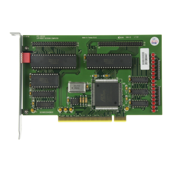
PCIカード Decision-Computer 8255-P2のPDF マニュアルをオンラインで閲覧またはダウンロードできます。Decision-Computer 8255-P2 8 ページ。

Port 1
(CN1)
The pin assignment of port 1/2 on page 8/9 in the original manual does not conform to the stan-
dards. The marking of pin 1 on the assembly print must be exchanged with pin 2.
Attention: If you connect directly to the post the original manual fits.
If a flat cable is plugged in, this pin assignment is valid.
D-Sub-37
IDC 40-Pin
1
PIN 1 rote Ader GND
2
3
3
5
4
7
5
9
6
11
7
13
8
15
9
17
10
19
11
21
12
23
13
25
14
27
15
29
16
31
17
33
18
35
19
37
frei
39
The load capacity of the outputs is about 1.8 mA. Caution - in old building instructions the old
8255 version is sometimes loaded with 10 mA!
The 16 LEDs indicate activity on the first two ports and are connected to the I/O lines
Signal
PA3
PA2
PA0
OUT0
CLK2
GATE2
GATE1
PA4
PA6
PC7
PC5
PC0
PC2
PC3
PB0
PB1
PB2
-5V
-12V
D-Sub-37
IDC 40-Pin
20
PIN 2
21
4
22
6
23
8
24
10
25
12
26
14
27
16
28
18
29
20
30
22
31
24
32
26
33
28
34
30
35
32
36
34
37
36
frei
38
frei
40
Signal
GND
GND
PA1
CLKO
GATEO
OUT2
CLK1
OUT1
PA5
PA7
PC6
PC4
PC1
PB7
PB6
PB5
PB4
PB3
+5V
+12V
