! Achtung ! Vorschriften von Arbeitsschutz und Um-
weltschutz beachten!
Bei großen Distanzen ist das meist nicht mehr mit einer
Messuhr möglich, da die Abstände der Wellen zu groß sind.
Hierfür empfiehlt sich ein lasergestütztes Wellenausrich-
tungssystem.
6.3. Montage der Distanzkupplung
6.3.1. Halbschalennabe
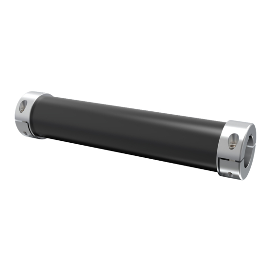
Bevor die Halbschalennabe auf
die Welle gesetzt wird, müs-
sen die Welle und die Bohrung
gründlich gereinigt und entfettet
werden. Danach kann der lose
Teil der Halbschalennabe auf
beiden Seiten demontiert und
die Kupplung auf die Wellen ab-
gelegt werden (siehe Abbildung
2). Nun können die losen Halbschalennaben
mit dem geeigneten Anzugsmoment (siehe 2.3) mit der
Distanzkupplung verschraubt werden.
6.3.2. Konusnabe
Bei der Konusnabe müssen ebenfalls die Bohrung wie die
Welle gereinigt und entfettet sein. Nach dem Aufziehen der
Nabe muss dann An-/ oder Abtrieb zusammengeschoben
werden. Hierbei darauf achten, dass die Konusnaben noch
frei auf der Welle sitzen und nicht an Maschinenteilen ansto-
ßen. Die Schrauben werden nun schrittweise „über Kreuz"
auf das volle Anzugsmoment angezogen. Dabei sind mehrere
Umläufe notwendig. Das Aufziehen der Nabe ist dann be-
endet, sobald sich die Schrauben innerhalb eines Umlaufes
nicht mehr weiter drehen.
6.4. Demontage der Distanzkupplung
Die Demontage der Kupplung erfolgt in umgekehrter Reihen-
folge zur Montage.
! Achtung ! Das Abziehen der Naben durch Schlagen
mit dem Hammer ist unzulässig und kann die Lager
der Maschine beschädigen.
Für die Konusnaben befinden sich zusätzliche Abdrückge-
winde in der Nabe, wodurch ein leichtes Abziehen der Naben
gewährleistet ist. Dafür einfach sämtliche Befestigungs-
schrauben komplett heraus schrauben und in die daneben-
liegenden Gewinde einschrauben. Nun kann der Konusring
(siehe Abbildung 1) sicher von der Nabe abgezogen werden.
7. Inbetriebnahme
Vor Inbetriebnahme der Kupplung ist sicherzustellen, dass
alle Schrauben richtig angezogen sind. Danach ist eine Ab-
deckung gegen unbeabsichtigtes Berühren anzubringen.
Während des Betriebs sind die vorgegebenen technischen
Parameter unbedingt einzuhalten. Insbesondere das maximal
zulässige Drehmoment und der maximal zulässige Wellenver-
satz sind zu beachten. Die Überschreitung dieser Werte kann
eine Beschädigung oder Reduzierung der Lebensdauer zur
Folge haben.
JAKOB Antriebstechnik GmbH
In case of large distances, this is usually no longer possible with
a dial gauge, as the distances between the shafts are too great.
A laser-based shaft alignment tool is recommended.
6.3. Assembly of the distance coupling
Abbildung 2 /
Illustration 2
6.3.2. Conical hub
In the case of the conical hub, the bore and the shaft must also
be cleaned and greased. After the hub has been pulled up, the
input / output must then be pushed together. Make sure that
the conical hubs are still seated freely on the shaft and do not
hit machine parts.
The screws are now tightened step by step „crosswise" to the
full tightening torque. Several circulations are necessary. The
winding up of the hub is finished as soon as the screws stop
turning within one revolution.
6.4. Disassembly of the distance coupling
The coupling is dismantled in the reverse order to the assembly.
There are additional forcing threads in the hub for the conical
hubs, which guarantees easy removal of the hubs. To do this,
simply unscrew all fastening screws completely and screw them
into the adjacent thread. The conical ring (see Figure 1) can now
be safely pulled off the hub.
7. Commissioning
Before putting the coupling into operation, make sure that all
screws are properly tightened. Then a cover must be attached
to prevent unintentional contact. The specified technical para-
meters must be strictly observed during operation. In particular,
the maximum permissible torque and the maximum permissible
shaft misalignment must be observed. Exceeding these values
can result in damage or a reduction in the service life.
|
! Danger ! Observe regulations on occupational safety
and environmental protection!
6.3.1. Half-shell hub
Before the half-shell hub is placed
on the shaft, the shaft and the bore
must be thoroughly cleaned and
greased. Then the loose part of the
half-shell hub can be dismantled on
both sides and the coupling placed
on the shafts (see Figure 2). Now
the loose half-shell hubs can be
screwed to the distance coupling
with the appropriate tightening torque (see 2.3).
! Danger ! Pulling off the hubs by hitting them with a
hammer is not permitted and can damage the bearings
of the machine.
|
www.jakobantriebstechnik.de
