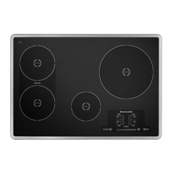
- ページ 4
クックトップ KitchenAid JIC4536XのPDF 技術シートをオンラインで閲覧またはダウンロードできます。KitchenAid JIC4536X 6 ページ。

FOR SERVICE TECHNICIAN'S USE ONLY
Service Code
Shown on Display
Failure Description
Type of Failure
Repair Suggestions
F-56
Wrong or invalid configuration
Type 3
1.
Disconnect power.
2.
Reconnect power.
3.
Reconfigure the cooktop following the directions in "Manual
Configuration Mode."
4.
If the issue is not fixed, disconnect power.
5.
Replace the User Interface.
6.
Replace all parts and panels before operating.
7.
Reconnect power.
8.
Reconfigure the cooktop following the directions in "Manual
Configuration Mode."
F-58
Wrong or invalid configuration
Type 2
1.
Disconnect power.
2.
Reconnect power.
3.
Reconfigure the cooktop following the directions in "Manual
Configuration Mode."
4.
If the issue is not fixed, disconnect power.
5.
Replace the power control board.
6.
Replace all parts and panels before operating.
7.
Reconnect power.
8.
Reconfigure the cooktop following the directions in "Manual
Configuration Mode."
F-60
Ul does not work
Type 3
1.
Disconnect power.
2.
Replace the User Interface.
3.
Replace all parts and panels before operating.
4.
Reconnect the power.
5.
Reconfigure the cooktop following the directions in "Manual
Configuration Mode."
F-61
Power control board does not
work
Type 2
1.
Disconnect power.
2.
Check that the cables between the User Interface and the power
control board are not damaged and are firmly plugged in.
3.
Check for 240 volts AC at the J1 connector on the power control
board by completing the following steps.
4.
Connect voltage measurement equipment.
5.
Reconnect power and confirm voltage reading. If voltage is not
correct, disconnect power and have a qualified electrician check
the home power supply.
6.
If voltage is correct, disconnect power and replace the cable
between the User Interface and the power control board.
7.
Replace all parts and panels before operating.
8.
Reconnect power.
9.
Reconfigure the cooktop following the directions in "Manual
Configuration Mode."
C-81, C-82
Over temperature
Type 2
Not enough ventilation: Check the cooktop installation according to
the Installation Instructions. In particular, check the blower intakes.
Component Testing Chart
To check for proper voltage, complete the following steps:
1.
Disconnect power.
3.
Reconnect power and confirm voltage reading.
2.
Connect voltage measurement equipment.
4.
Disconnect power after performing voltage measurements.
Location on the cooktop
Checkpoints
Results Voltage
EMI filter board
J1 - (L) (N)
From 208VAC to 240 VAC -60Hz
Power control board (PC)
Left and right
J1 - (L) (N)
From 208VAC to 240 VAC -60Hz
Power control board (PC) to blower fan
Left and right
J205 - (00) - (22)
J205 - (00) - (60)
From OVDC to 12VDC
Power control board (PC) to the element
sensor
Left and right
J604 - (1) - (2)
J605 - (1) - (2)
+5VDC
0V
+10.5V
Power control board (PC) to the User
Interface
J806 - 00
J806 - 88
J806 - 99
J806 - 22
J806 - 44
(Each of these pins refers to J806 - 99
[OVDC, Neutral pin])
OVDC
From OVDC to 12VDC
4
