- ページ 11
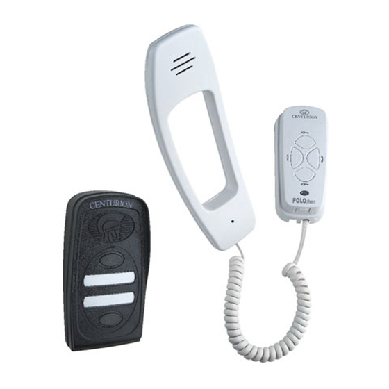
インターホン・システム Centurion POLOphoneのPDF インストレーション・マニュアルをオンラインで閲覧またはダウンロードできます。Centurion POLOphone 17 ページ。 Entry panel
Centurion POLOphone にも: インストレーション・マニュアル (16 ページ), インストレーション・マニュアル (17 ページ), 委託手続き (4 ページ)

9
80mm
Tighten cable tie ensuring that there
is sufficient slack to terminate the
cable onto the electronics (±80mm).
12
Terminate onto the electronics.
Refer to the wiring diagram (See
page 12)
15
A
Clip the (A) long tail end of the
telephone cord into the jack
provided at the bottom of the cradle
and similarly into the handpiece.
Replace the handpiece onto the
cradle.
10
Terminate cable onto electronics.
Refer to wiring diagram (See page
12).
13
Using a sharp knife carefully cut
out the cable entry slot to allow the
surface mounted cable to route into
the cradle.
Wiring the status LED
Wiring the status LED
1
Connect the wires from the status
LED on the gate motor to the
terminals.
Handset installation
11
Concealed
Cable route
If the cable is surface mounted,
route the cable into the unit from
underneath as shown. Secure to
cradle base using cable tie provided.
Allow sufficient slack (±80mm)
14
Clip the cradle back onto the base.
NB: It will be necessary when
commissioning the unit to
have the cradle cover
removed.
2
Insert the wire from the LED drive
in the gate motor into the terminal
marked with a ( ).
Insert the wire from the COM/-
from the gate motor into the
terminal marked with a ( ).
POLOphone Intercom - Page 11
80mm
*
*
