- ページ 11
試験装置 Major tech MT473のPDF ユーザーマニュアルをオンラインで閲覧またはダウンロードできます。Major tech MT473 16 ページ。 Voltage tester

5. Operation
5.3 Single-pole phase Test
• The single-pole phase test is only possible when batteries are installed
and in good condition.
• The single-polephase test starts at an AC voltage of approx.100V
(pole>100V AC).
• When using single-pole phase tests to determine external conductors the
display function may be impaired under certain conditions (e.g. for
insulating body protective equipment on insulation locations).
• The single-pole phase testing is not appropriate to determine whether a
line is live or not. For this purpose, the double-pole voltage test is always
required.
• Connect both test probes with power source.
• A signal sound indicates the phase.
• The "
" LED is illuminated in the display
5.4 Continuity Test
• The continuity test is only possible when batteries are installed and in
good condition. A signal sound is audible for continuity and the LED for
continuity LED
5.5 Voltage Test with Switched Load, RCD Trip Test
• During voltage tests, you can decrease the interference voltages from
inductive or capacitive coupling by loading the UUT with a lower
impedance than the Tester has in normal mode. In systems with RCD
circuit breakers, you can trip an RCD switch with the same low
impedance as when you measure voltage between L and PE.
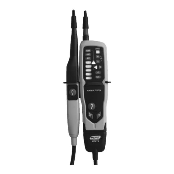
• To do an RCD trip test during voltage measurement, push the two low
impedance buttons (14)at the same time. If you have 10 mA or 30 mA
RCDs between L and PE in a 230 V system, it will trip.
• During load current, the indicator probe side vibrates and the low
impedance LED is the indication for the flowing load current. This
indication is not to be used for voltage test or measurement.
• If the two pushbuttons are not used, the RCDs will not trip, even in
measurements between L and PE.
(6) is illuminated.
11
