- ページ 6
試験装置 Major tech MT500のPDF 取扱説明書をオンラインで閲覧またはダウンロードできます。Major tech MT500 8 ページ。 Analogue insulation tester

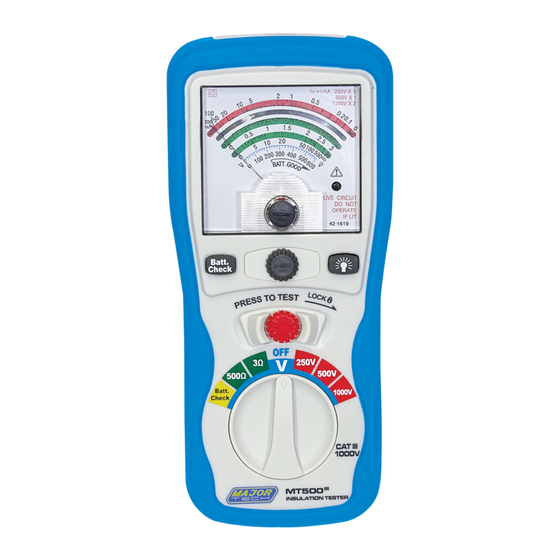
4. PARTS & CONTROLS
1. Point needle
2. Lock Button
3. 0-Adjust Button
4. Backlight Button
5. Test Button.
5. HOW TO CONNECT TEST LEADS.
a) On MΩ Range: Connect the red test lead into the "VΩ" terminal
and the black lead into the "COM" terminal.
b) On3Ω/500Ω and ACV Range: Connect the red test lead into the
"VΩ" terminal and the black lead into terminal "COM"
6. INSULATION RESISTANCE MEASUREMENTS
6.1. Measurements at 200MΩ/500V
This is the voltage used for the majority of insulation resistance tests on
normal installation requirement. To measure insulation resistance, press
the test button to power on the tester. The point needle will displayed
the insulation resistance. Section VII indicated that subdivision of large
installations might be necessary because of the large number of parallel
insulation resistance. In such a case, an installation may be divided into
sections, each being separately tested. Each section must have not less
than fifty outlets, an outlet being a switch, socket, lighting point etc. A
switched socket counts as one outlet. The minimum acceptable
insulation resistance is 1MΩ. For a large installation, the capacitance of
6
6. Rotary Function switch
7. VΩ Jack
8. COM input jack
9. Pothook
10. Battery Cover
