- ページ 8
試験装置 Major tech MT560のPDF 取扱説明書をオンラインで閲覧またはダウンロードできます。Major tech MT560 12 ページ。 Digital insulation tester

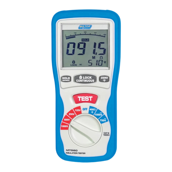
TEST: In the insulation resistance testing function, pressing and
holding the "TEST" button, the meter will inject high-voltage, and
enter into the insulation resistance testing, release the "TEST" button and it
will cut off the high-voltage and exit form the insulation resistance testing.
ZERO/LIGHT: Press the "ZERO/LIGHT" button, the current values in the
primary display will be set to zero, (mainly used for 400Ω, the low
resistance testing), it will return if the button is pressed for 2 seconds, it
will enter directly into the "LIGHT" status, and the LCD backlight light up.
After 15 seconds, the backlight is shut off automatically, the same as
pressing for 2 seconds within 15s.
b) Display Indicators
The Primary Display : Indicates the current function testing values
The Secondary Display : It shows the output DCV while you test the
insulation resistance, and the battery voltage while the ACV
The Analog Bar : Indicates the current function testing value in
synchronous with the primary display.
:While testing the insulation resistance, the symbol " " flashes
frequently if the voltage is over 30V.
: While testing the insulation resistance, the symbol "
frequently and the buzzer warns continually if the outside voltage is
over 30V. the symbol "
buzzer warns continuously.
LOCK: Push down the "LOCK" button while you test the insulation
resistance and the symbol "
LOBAT : The display shows "LOBAT" when the voltage drops below 7.5V
MAX/MIN: Stand for the maximum or the minimum.
ZERO: Digital zero adjusting.
HOLD:The digital holding function for the primary display.
AC, DC: The indicator for the voltage property.
V, MΩ, Ω: The measured dimension units.
5. INSULATION RESISTANCE MEASUREMENTS
a) Turn the function switch from the "OFF" position to the left (4000MΩ/
1000V, 4000MΩ/500V, 4000MΩ/250V, 1000MΩ/125V) and choose one
of the voltage-block (there are 4 ranges namely, 4MΩ, 40MΩ, 400MΩ
and 4000MΩ can be switched automatically for every voltage-block.)
b) Connect two testing lines to the tested ;
c) Push down and hold the "TEST" button /or press the "LOCK" keystoke
first and then the "TEST" button, if the object under test is live and its
voltage (AC/DC) is over 30V, it will refuse to work and no high-voltage
testing occurs, simultaneously, it shows ">30V" on the LCD, the symbol
" " flashes, and the buzzer warns frequently. If the object under test
8
" is indicated while LOΩ≤35Ω and the
" is indicated.
" flashes
7
