- ページ 10
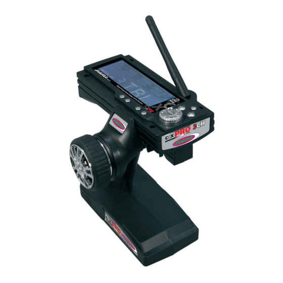
送信機 Jamara CCX Pro 2,4 GHzのPDF 取扱説明書をオンラインで閲覧またはダウンロードできます。Jamara CCX Pro 2,4 GHz 20 ページ。
Jamara CCX Pro 2,4 GHz にも: 取扱説明書 (20 ページ), インストラクション (12 ページ), 取扱説明書 (20 ページ)

LED
Receptor
Receiver
ES - Enlace de la emisora con el receptor
En un moderno sistema de 2,4GHz, es imprescindible que la emi-
sora y el receptor están unidos en el modelo. El receptor acepta
sólo los signales de su emisora.
Una vez que se no realiza el enlace, por favor, haga lo siguinte:
A. Coloque la batería cargada en la emisora o pilas nuevas. Deje la
emisora desenchufada.
B. Coloque el cable de conexión de los tres canales.
C. Encender la emisora, mientras haces el bindingde la batería con
el receptor. Depende de la versión del software, señala su
receptor varios modo de binding (en vez de parpadear, la LED
brilla o esta apagado). El binding es siempre lo mismo en todas
las versiones. La LED en el receptor impieza a parpadear y indica
que el receptor no esta en el modo binding.
D. Pulse el botón de encendido de la estación y, al mismo tiempo
cambiar el canal.
E. La emisora impieza a parpadear y indica que estas en el modo
binding.
F. Quitar el dedo el botón de encendido de la emisora y retirar del
enchufe del receptor.
G. Quitar el dedo el botón de encendido de la emisora y retirar del
enchufe del receptor.
H. Cuando haga la instalación, tratar de hacer todo
correctamente.
I.
Si no hay éxito en el procedimiento, vuelva hacerlo todo otra
vez.
La siguiente fi gura muestra gráfi camente el proceso de unión e
identifi ca los elementos que deben ser.
10
Clave de enlace
Binding Button
Batería
Battery
Conexión de enchufe
Binding Plug
GB - Binding the receiber to the transmitter
As with all modern 2.4GHz R/C systems the receiver must be bound
to the transmitter to ensure that the receiver will only react to
signals from that transmitter.
If you wish to re-bind the receiver with the transmitter please pro-
ceed as follows:
A. Ensure that the transmitter is fi tted with fresh or fully charged
batteries and leave the transmitter off.
B. Plug the binding plug (included) into the channel 3 socket on
the receiver.
C. Switch the receiver system on by connecting the battery or
turn in a BEC operating on a controller to control. Depending
on your software version of your receiver indicates the different
binding mode (instead of fl ashing lights for example LED or
remains out completely). The binding process as such is in all
versions. The receiver LED will begin to fl ash indicating that the
receiver is in bonding mode.
D. Press and hold down the binding button on the transmitter
whilst switching it on.
E. The transmitter will begin to fl ash indicating that the receiver
is in bonding mode.
F. Release the binding button on the transmitter and disconnect
the receiver from the battery or turn off the controller.
Release the binding plug from the receiver.
G. Switch of the transmitter. and remove the binding wire. The
system be bound at the next start ..
H. Install all properly and check anything very precisely.
I.
If the receiver fails to bond or does not function after bonding
repeat the above procedure until a successful bonding is
achieved.
The following diagrams illustrate the bonding process and show
the locations of the relevant components.
Bindungsstecker
