- ページ 2
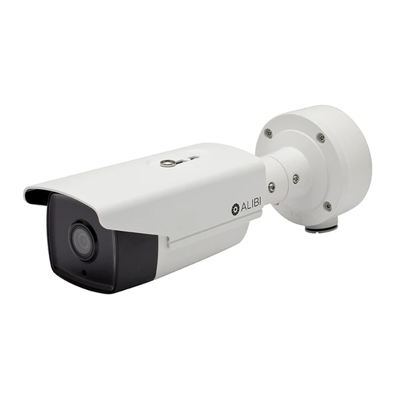
防犯カメラ ALIBI ALI-NS4028RのPDF クイック・インストール・マニュアルをオンラインで閲覧またはダウンロードできます。ALIBI ALI-NS4028R 6 ページ。 Ip bullet cameras
ALIBI ALI-NS4028R にも: クイック・インストール・マニュアル (5 ページ)

7.
Attach the camera safety cable to the safety hook inside the junction box.
To mount the camera onto a surface without the junction box
For this mounting option, the drop cables can be routed through the mounting surface, or through the
cable channel in the mounting base.
Mounting base
screws (4)
1.
Determine the best fasteners for securing the camera mounting base to mounting surface. The
mounting hardware provided may be suitable for some surfaces.
2.
Remove the junction box from the camera assembly by removing the four mounting base captive
screws.
3.
Using the camera mounting base as a template, mark the locations of the holes for the mounting
screws. Also mark the location of a hole for the camera drop cables if needed.
4.
Route extension cables from the power source and LAN switch (or LAN with PoE) to the
mounting location.
To mount the camera onto an electrical box
1.
Install a double-gang electrical box at the location where the camera will be installed.
2.
Attach the adapter plate provided to the electrical box using four (4) screws.
Double-gang box
Adapter plate
Adapter plate mounting screws (4)
3.
Remove the junction box from the camera assembly by loosing the four mounting base captive
screws.
4.
Attach the adapter plate to the double-gang box using at least two (2) screws.
5.
Route extension cables from the power source and LAN switch (or LAN with PoE) into the
electrical box, and then up through the cable opening in the adapter plate.
Step 2.
Connect camera drop cables to LAN and power
1.
Connect the network LAN and power extension cables to the camera drop cables:
a.
Connect the Ethernet LAN cable to the camera LAN drop cable. Protect the connection
from moisture and other contamination, if necessary. A Weatherproof Ethernet Fitting is
provided. Installation instructions for the fitting are included at the end of this document.
Camera
Network drop cable
from camera
Weatherproof Ethernet Fitting installed
2
www.observint.com
Mounting surface
Cable channel
Camera
Orientation mark
Camera
Mounting base screws (4)
Ethernet switch
Network cable from
router or switch
Failure of the power or Ethernet connector due to moisture or another
!
contaminant is considered an installation error, which voids the warranty. If
installing this camera in a location such as an overhang, shop, garage, kitchen,
WARNING
etc. where high humidity or dust is present, seal these connections adequately.
b.
If the camera is not powered using PoE (Power over Ethernet injector), connect the 12 Vdc
power cable to the camera drop cable. The polarity of the drop cable connector is shown
below.
Do not apply power to the camera at this time. Before applying power to the camera, ensure
that the polarity is correct. An incorrect connection may cause a malfunction and can damage
CAUTION
the camera.
2.
Secure the camera to the mounting surface or Junction box using appropriate screws.
3.
Apply power to the camera through the 12 Vdc power cable or PoE injector, as configured.
Step 3.
Install the Alibi Config Tool software
NOTE: If the camera LAN extension cable is attached to a Network Video Recorder (NVR), skip this step.
The Alibi Config Tool is a PC-based network utility for discovery of Alibi compatible devices. It provides
an easy way to activate devices, configure camera and recorder network configuration settings, and set
device passwords. It can be installed on a Microsoft® Windows® operating system that has direct access
to the network where your Alibi devices are installed. You can download the Alibi Configuration Tool
from Supercircuits.com or AlibiSecurity.com/Resources.
1.
Download the Alibi Config Tool from the Supercircuits.com or AlibiSecurity.com/Resources
website. At the time when this document was published, the file is named: alibi-config-tool.
zip and is about 80MB.
2.
Un-zip the file on a computer with Microsoft Windows (Windows 7 or newer) that is connected
to the LAN where your Alibi camera is connected.
Run the file contained in the zip file: Alibi Config Tool.exe. Follow the on-screen instructions
3.
to install the file.
4.
Open the Alibi Config Tool application. When the application opens, it automatically "discovers"
and lists all Alibi compatible devices on the LAN. See below.
Notice: In the screen above, the tool discovered devices with IP addresses of 192.168.3.xxx. It will
also list other Alibi compatible devices on the LAN, and devices with the address 192.168.1.64 (an
inactive Alibi device).
Step 4.
Activate Inactive Alibi device
NOTE: If the camera LAN extension cable is attached to a Network Video Recorder (NVR), skip this step.
Refer to the documentation available for your NVR firmware for the procedure to activate the camera, if
necessary.
When an Alibi device is first installed, or reset to its factory configuration, it must be "Activated" before
it can be used. In the Alibi Configuration Tool, "Inactive" devices have a Security status of Inactive,
and an IPv4 address of 192.168.1.64. A device is "Activated" when a password is assigned to the
admin username of the device.
In the example below, an ALI-NS4022R camera is activated and configured for its network. The
procedure is similar for all other Alibi network cameras currently available.
© 2017, 2018 Observint Technologies. All rights reserved.
