- ページ 8
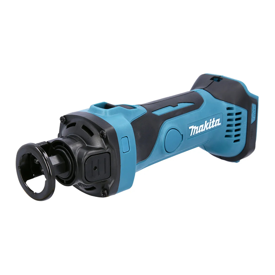
電動工具 Makita DCO140のPDF 技術情報をオンラインで閲覧またはダウンロードできます。Makita DCO140 8 ページ。 Cordless cut-out tool
Makita DCO140 にも: 取扱説明書 (13 ページ), 取扱説明書 (13 ページ)

W
iring diagram
Fig. D-2
Attach Receptacles to the tabs inside Switch.
Attach Insulated terminals to Switch as shown below.
Receptacle (2 pcs.)
Place Connectors in this space.
Controller
Terminal
Rib of Controller
Put Lead wires connected to Terminal
under the rib on Controller.
Switch
Insulated terminal (2 pcs.)
Boss
Do not put Lead wires on this rib.
Pass black lead wire and red lead wire from Endbell complete
through Line filter, and then place Line filter in this space between
Boss and Endbell complete (when Line filter is used.)
Do not pinch Lead wires connected to Switch
between the ribs on Housing L/R and Endbell complete.
Ribs on Housing L
Cross-section betweenA and A'
A
A'
Endbell complete
P 8/ 8
Ribs on Housing R
Endbell complete
