Page 6
ENGLISH
Section 3. Installation Instructions
WARNING
Use equipment only in a pool or spa installation. Do not
connect system to an unregulated city water system or
other external source of pressurized water producing
pressures greater than 35 psi.
3.1
Filter Location
1.
Select a well-drained area, one that does not flood
when it rains. Damp, non-ventilated areas should
be avoided.
2.
The filter should be installed on a firm, solid, and
level surface or platform to avoid risk of settlement.
Do not use sand to level the filter as the sand will
wash away; filter systems can weight up to 800
pounds once loaded with media. Check local
building codes for additional requirements. (Ex.
Equipment pads in Florida must be concrete and
equipment must be secured to the pad.)
3.
Install electrical controls at least five (5) feet from
the filter. This will allow enough room to stand
away from the filter during start-up.
4.
Allow sufficient clearance around the filter to permit
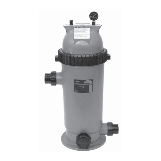
a visual inspection of the clamp ring. See Figure 2.
5.
Allow sufficient space above the filter to remove
the filter lid and filter element for cleaning and
servicing.
6.
Position the filter to safely direct water drainage.
Align the air release valve to safely direct
pressurized purged air or water.
WARNING
Water discharged from an improperly positioned filter
or valve can create an electrical hazard which can
cause death, serious injury or property damage.
CAUTION
Maintain your pressure gauge in good working order.
The pressure gauge is the primary indicator of how the
filter is operating.
6" MINIMUM CLEARANCE
FILTER
Figure 2.
Filter Location
Jandy
DE Pool Filters
®
6" MINIMUM
CLEARANCE
|
Installation & Operation Manual
7.
If the filter needs to be located above the water
level of the pool, it can be raised 2.5 ft. without
affecting the pump efficiency. A check valve is
recommended on the suction line to the pump.
8.
If the filter is to be installed below the water level
of the pool, isolation valves should be installed on
both the suction and return lines to prevent back
flow of pool water during any routine servicing
that may be required.
3.2
Anchor Bracket Installation
In Florida, building codes require that all appliances
be securely fastened to the equipment pad in order to
withstand high wind pressures created by hurricanes.
Zodiac Pool Systems, Inc. provides an anchor bracket kit
for this purpose. Please see the Parts List in Section 9 of
this manual for the correct part number.
NOTE
Anchor screws and washers are not included with the
filter or the anchor bracket kit. Zodiac
that a ¼" x 2¼" long stainless steel Tapcon
concrete screw be used to mount the anchor bracket
to the equipment pad. The Tapcon type concrete screw
meets Florida buliding code requirements.
After placing the filter on the equipment pad, as outlined
in Section 3.1, drill a 5/32" hole in the concrete at each of
the four (4) brackets on the filter. (The correct size drill
bit is usually provided with the concrete screws when
purchased.)
Install the Tapcon screws and washers through each of
the four (4) anchor brackets to secure the filter to the
equipment pad. See Figure 3. Do not over-torque the
screws.
3.3
Filter Preparation
1.
Check carton for damage due to rough handling
in shipment. If carton or any filter components are
damaged, notify carrier immediately.
2.
Carefully remove the accessory package.
3.
With the carton in an upright position, remove the
filter tank from the carton.
CAUTION
DO NOT move the filter tank without the shipping
screw in place or the filter grids may be damaged while
installing the filter tank.
4.
A visual inspection of all parts should be made
now. See the parts list on page 15.
®
recommends
type
®