- ページ 17
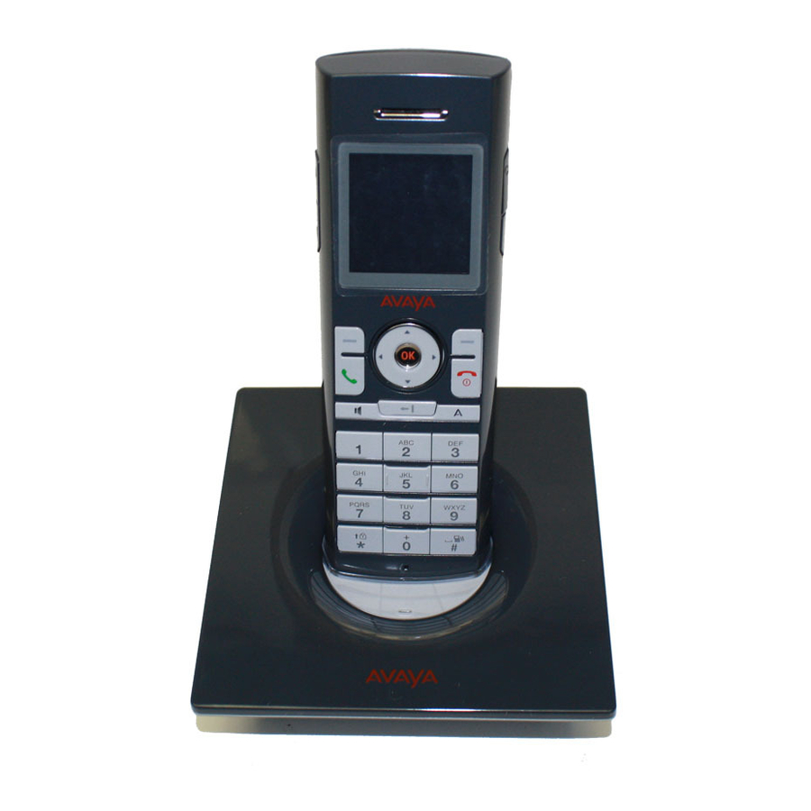
電話 Avaya 3645のPDF インストレーション・マニュアルをオンラインで閲覧またはダウンロードできます。Avaya 3645 19 ページ。 Co-existence with ip wireless handset offering
Avaya 3645 にも: クイック・リファレンス・マニュアル (2 ページ), 設定マニュアル (8 ページ)

Installation Guide
Avaya wireless telephones can be deployed across multiple subnets when used with an IP telephony
server interface if the performance requirements outlined below are met. One of two deployment
scenarios described below can be used, depending on needs and infrastructure capabilities, keeping
in mind that the Avaya wireless telephones will never actively roam across a subnet boundary without
power-cycling the handsets unless a VIEW Certified layer-3 roaming infrastructure is used in
accordance with the VIEW deployment guidelines.
In one deployment scenario for accommodating multiple subnets, each subnet is treated
independently with respect to the AVPPs and wireless network, but each subnet can still provide
service to a single IP telephony server. One or more AVPP(s) can be deployed on each subnet just as
with a single subnet system, including identifying each Registration AVPP IP address via DHCP or
static configuration. In the second scenario, a single AVPP (or set of AVPPs) is deployed, generally
on the same subnet as the IP telephony server. The Registration AVPP is identified to all phones via
DHCP or static configuration, regardless of what subnet the phone is operating in. This scenario
requires less AVPPs to be installed, but requires higher performance from the router (see performance
requirements below).
The ability to cross a subnet boundary exists in either scenario, but the Avaya handsets will need to be
power cycled to obtain new IP address within the new subnet. In addition, other configuration
considerations must be addressed. Because users will not want to re-administer the wireless
telephones to a separate subnet, Extended Service Set Identifications (ESSIDs) should be the same
or the handsets should be set to the "Learn Always" mode, the security mode and associated key
should be the same or turned off, and DHCP should be used.
6.2 Network Performance Requirements
Ethernet packets containing voice as their payload have short, useful lifetimes, making the timely
delivery of voice packets essential. Routers can introduce latency and delay between the AVPP and
the APs, resulting in poor voice quality.
Ethernet connectivity from the IP telephony server or other voice endpoint to the AVPP should never
exceed 100 milliseconds of network delay (one way), 30 milliseconds of network jitter, and 2 percent
packet loss end to end regardless of the physical properties of the link. The link from the AVPP to the
APs should be under 100 milliseconds of network delay, one millisecond of jitter and under two
percent packet loss. In both cases, the jitter requirements are for wired network jitter and do not
include the RF link.
One feature of the AVPP is to control the timing of packets through the AP. The delay between the
AVPP and the AP does not need to be strictly controlled as long as it is consistent. The jitter
requirement between the IP telephony server and the AVPP is a function of how the audio is
packetized for encapsulation and the packet queuing in the AVPP.
Jitter between the AVPP and the AP should be measured at the wired Ethernet connection to the AP.
If the AP is an AP switch attached to lightweight APs and products are VIEW Certified the system,
jitter can be measured at the entry to the AP switch. For this measurement, assume the AVPP is
delivering packets at 30 millisecond intervals with no jitter. The time is measured from the arrival of
one packet from the AVPP directed to a single wireless telephone to the next packet from the AVPP to
the same wireless telephone. The jitter measurement is the time difference from the ideal 30
millisecond arrival of packets at the AP.
Octiober 2008
17
