- ページ 10
マザーボード Broadcom ACPL-352JのPDF リファレンス・マニュアルをオンラインで閲覧またはダウンロードできます。Broadcom ACPL-352J 15 ページ。 Vincotech h6.5 3-level igbt flowpack module evaluation board
ACPL-352J Reference Manual
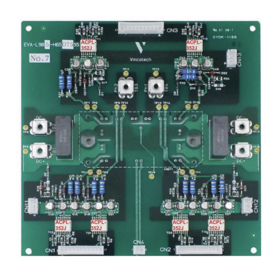
Vincotech H6.5 3-Level IGBT flowPACK Module Evaluation Board
During overcurrent fault condition, the IGBT is soft shut down through the SS pin and the rate of shut down can be adjusted
by R14.
The gate resistors (R15/R16) serve to limit gate current and indirectly control the IGBT switching times. Diode, D1 is used
together with the CLAMP function to shunt parasitic IGBT Miller current during the off cycle.
The gate resistors can be calculated from the secondary side power supply and I
specification of ACPL-352J:
O(PEAK)
This negative going voltage spike is typically generated by inductive loads or reverse recovery spike of the IGBT
freewheeling diodes. Zener diode, D14 and Schottky diode, D11 are used to prevent a false fault signal caused by positive
and negative spikes.
The complete schematic is show in
Figure
10.
Broadcom Confidential
ACPL-352J-Ref-RM100
10