- ページ 13
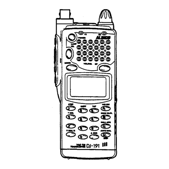
レシーバー Alinco DJ-191のPDF 取扱説明書をオンラインで閲覧またはダウンロードできます。Alinco DJ-191 18 ページ。 Cert communications team procedures
Alinco DJ-191 にも: 取扱説明書 (18 ページ), クイック・リファレンス (3 ページ), クイック・リファレンス (4 ページ)

III
20
Note: The following rules apply to channel steps as indicated.
1. When 5kHz channel step is selected, keys "0" and "5" are available for
entry into the 1kHz digit. (Last digit entry other than "0" or "5" will be taken
as
"0".)
2. When 10kHz channel step is selected, keys "0", "1", "2",
"3", "4",
"5",
"6", "7",
"s"
and
"9"
are available for entry into the 10kHz digit.
3.
When 12.SkHz channel step is selected, keys "0", "1", "2",
"3",
"5",
"6",
"7"
and
"s"
are available for entry into the 1OkHz digit.
4.
When 15kHz channel step is selected, keys "0", and "5" are available for
entry into the 1kHz digit. (Last digit entry other than "0" or "5" will be taken
as
HO".)
5. When 20kHz channel step is selected, keys "0", "1", "2",
"3", "4",
"5",
"6", "7",
"S",
"9"
and "0" are available for entry into the 10kHz digit.
6.
When 25kHz channel step is selected, keys "0", "2", "5" and
"7"
are avail-
able for entry into the 1OkHz digit.
7.
When 30kHz channel step is selected, keys "0", "1", "2",
"3", "4",
"5",
"6", "7",
"S",
"9"
and "0" are available for entry into the 10kHz digit.
CHANGING FREQUENCY IN ONE MHz STEPS
In the VFO Mode, pressing and holding the
II
key, rotate the Main Tuning Dial.
This will change the frequency Up or Down in one MHz Steps.
CLEARING ENTRY
To clear an error during keypad entry, you may press the PTT switch to exit and start
over again.
8-2 Transmitting
cautions: Ensure that you always use the original rubber duckie antenna or
an
external antenna with low SWR (Standing Wave Ratio) readings.
Improper antenna connection may
cause
damage
to
the radio and may
void warranty.
1. Make sure that you follow all steps set forth in the
"6.
GETIING STARTED" section
first.
2. Select a frequency, shift direction, shift value and CTCSS Tone (Sub-Audible Tone)
frequency.
3.
Check to see that the frequency is not in use before transmitting.
4.
Select appropriate transmitter output level.
5. Press and hold the PTT switch and speak approximately 1Ocm or
3
H
from the micro-
phone located on the front bottom of the radio.
8-3 Transceiver Modes
Your transceiver
has
3 modes; VFO mode, MEMORY mode and CALL mode.
VFO (Variable Frequency Oscillator) MODE
The transceiver will be in the VFO mode. This mode is used to change frequency
and select the desired channel step, offset frequency shift direction, tone frequency
(encoder and decoder), tone setting, DSQ code, DSQ setting, Power H/L, and
as
(battery save ON/OFF).
MEMORY MODE
The following guidelines will help you to program and manipulate memory channels.
In the Memory mode, memory channels can be reviewed. To select the Memory mode,
press the
~
key.
PROGRAMMING A MEMORY CHANNEL
To write VFO informations into a memory channel, perform the followings.
1. Enter the MEMORY MODE.
2. Rotate the Main Tuning Dial to choose the desired memory channel number
(clockwise to increase, counter-clockwise to decrease). Select the desired memory
channel number (0 to 39).
3.
If the Memory Channel Number is flashing, it indicates the memory channel is
vacant. A non-vacant channel can be over-written with new data.
4.
Enter the VFO mode.
5. Select the receive frequency.
6.
Select the shift
II
or
II,
or none.
7.
Select the required offset (Consult your Repeater Directory) if shift is required.
S. Select the proper CTCSS Tone (Sub-Audible Tone) if needed.
9.
Select the Tone Squelch if needed (An optional Tone unit (EJ-2SU) is required).
10. Other data, such as DSQ code, DSQ activation, Power H/L, and
as
(battery save
OFF/ON) may
be
set, if
so
desired to memorize into the channel.
11. Press and hold the
II
key, and press the
~
key to write (store) the information to
the memory.
SCROLL MEMORY
Scrolling memory channels up or down can be accomplished as followings;
1. Select the MEMORY MODE. The memory channel number (0-39) will appear.
2. Turn the Main Tuning Dial to increase or decrease the memory channel.
21
