- ページ 30
カーナビゲーションシステム Garmin Cessna Caravan G1000のPDF 飛行機フライトマニュアル補足をオンラインで閲覧またはダウンロードできます。Garmin Cessna Caravan G1000 33 ページ。 Integrated flight deck
Garmin Cessna Caravan G1000 にも: パイロット・マニュアル (16 ページ), パイロット・マニュアル (6 ページ), パイロット・マニュアル (32 ページ), パイロット・マニュアル (25 ページ), パイロット・マニュアル (34 ページ), パイロット・マニュアル (21 ページ), パイロット・マニュアル (22 ページ)

AFM SUPPLEMENT
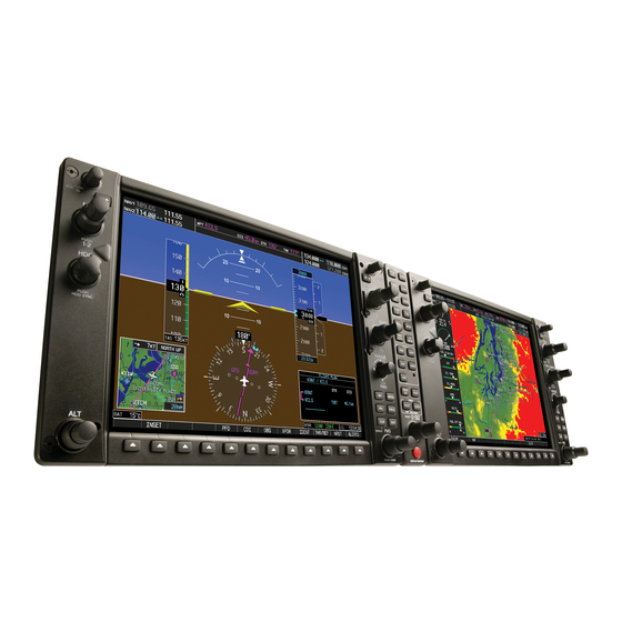
GARMIN G1000 INTEGRATED AVIONICS SYSTEM
G--1000 Cockpit Reference Guide for the Mooney M20R.
Traffic data detected by the L--3 Communications Goodrich SKY-
WATCHt Traffic Advisory System (TAS), if installed, will appear on the
MFD and traffic display pages of the G--1000. For detailed operating in-
structions regarding the interface of the G--1000 with the SKYWATCHt
refer to the Pilot's Guide for the SKYWATCHt and the Garmin G--1000
Cockpit Reference Guide for the Mooney M20R.
Refer to the GARMIN G1000 Cockpit Reference Guide for the M20R
MODEL aircraft, GARMIN P/N 00--00450--01, Rev. A or later FAA ap-
proved, for complete descriptions of the G1000 system and operating
procedures.
7.1 - - LANDING GEAR
Gear down and locked positions are indicated by a single indicator lo-
cated on the aircraft floor and a red "GEAR WARN" light is located in the
system indicator lights, as well as a green "GEAR DWN" indicator. Re-
fer to the aircraft POH/AFM for additional information.
7.2 - - ELECTRICAL SYSTEM
The M20R has a 28 Volt DC system, powered by a 100--amp alternator
which is mounted on the front of the engine. It is driven by the engine
crankshaft through a shear mechanism and charges the main batteries.
The alternator is the primary source of aircraft power and is connected
to the aircraft electrical system at the main bus. In the event of an alter-
nator failure, the ship's battery provides the system with electrical pow-
er, in conjunction with a 20 Amp standby alternator that is actuated by
the pilot using a manual switch in the cockpit labeled EMER BUS.
Power is stored in two 11 amp--hour lead acid battery which are
mounted in the tailcone of the aircraft, and either battery may feed both
the essential and non--essential busses. In the event of an alternator
failure, the standby alternator and selected main battery will power the
following:
A reduced subset of the G1000 system, which is comprised of the
S
PFD/MFD, AHRS, ADC, Com1, Nav1, GPS1, transponder, audio
panel, and Engine Instruments;
An independent, standby attitude indicator (artificial horizon);
S
Lighting for the attitude indicator, altimeter, airspeed indicator, and
S
compass;
Aux. Overhead Equipment, Aux Panel Equipment, and Ice Protec-
S
tion System.
When the EMER BUS switch is set to ON, the Emergency Bus annun-
ciator is activated, the Standby Alternator is energized and brought on
line The standby alternator is capable of powering a limited amount of
30 of 33
FAA APPROVED
MOONEY
M20R
ISSUED 11 - 2004
REVISION A 06--2005
REVISION B 03--2006
