- ページ 25
アビオニクス・ディスプレイ Garmin 011-01257-20のPDF インストレーション・マニュアルをオンラインで閲覧またはダウンロードできます。Garmin 011-01257-20 47 ページ。

3.6
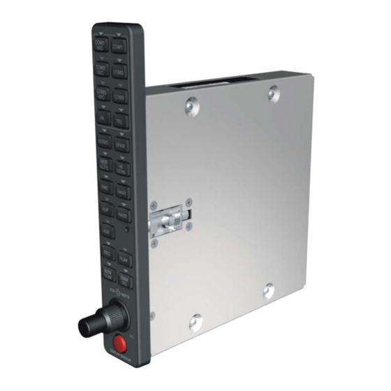
GMA 1347D Unit Installation
Do not use excessive force when inserting the GMA 1347D into the rack. This may
damage the connectors, unit, and/or unit rack.
installation, stop! Remove the GMA 1347D and identify the source of resistance.
For final installation and assembly, refer to the outline and installation drawings shown in Appendix A of
this manual.
1. Assemble the backshell as described in Section 3.5.
2. Connect both backshells to the rear plate using the screws provided in the connector kit.
3. Mount the unit rack to a suitable mounting location on the panel using the provided nutplates.
4. Assemble the rear plate into the GMA 1347D unit rack.
5. Insert the GMA 1347D into the rack, noting proper orientation as shown on the installation
drawing in Appendix A.
6. Lock the GMA 1347D in place using the appropriate size hex wrench.
3.7
Post Installation Configuration and Checkout
The GMA 1347D does not provide valid outputs until the aircraft post installation
configuration procedures are completed.
The GMA 1347D must be installed with a Garmin G1000 system and have FAA approved configuration
data. Configuration data is loaded to the GMA 1347D from an aircraft-specific G1000 SW Loader Card.
The G1000 PFD serves as the graphical user interface to be used by the installer that is configuring the
system. For basic configuration information, refer to the G1000 Line Maintenance and Configuration
Manual, Garmin part number 190-00303-04. For actual aircraft installation/checkout, use only aircraft
manufacturer approved checkout procedures.
3.8
Continued Airworthiness
Other than for regulatory periodic functional checks, maintenance of the GMA 1347D is
"on condition" only.
GMA 1347D Installation Manual
190-00303-21
CAUTION
If heavy resistance is felt during
NOTE
Page 3-3
Revision C
