- ページ 3
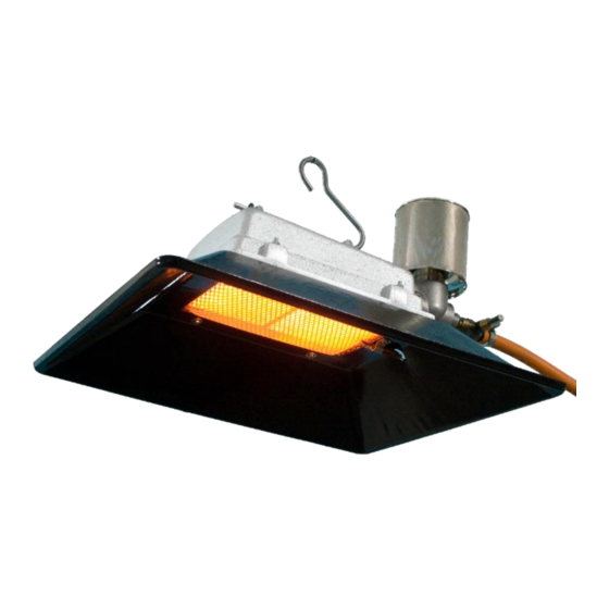
ヒーター Alke 61 SeriesのPDF ユーザー・インストール・マニュアルをオンラインで閲覧またはダウンロードできます。Alke 61 Series 8 ページ。 Atmospheric ceramic luminous infra-red heaters for use in well ventilated areas
Alke 61 Series にも: ユーザー、サービス、インストールマニュアル (13 ページ)

Keep always a safe distance around the gas heater to other materials and walls. See the table below for the
minimum safety distances. The operational distances are guidelines to start with. Adjust later on to the correct
height based on your personal preference and experience. For non-agricultural installations keep a distance of
at least 2,0 meters from floor to the heater.
Operational Distances
To the animals
Minimum Safety Distances to
combustible materials
To the ceiling
To the sides
Under the heater
Heater installation
A guideline for placement of the sensor of the temperature regulation is 60 cm above the ground and minimal
40 cm away from a heater. Use sensors with a black surface in case the regulation is based on measuring the
infra red temperature.
Gas cylinders
Keep full or empty gas cylinders away from any heat source and keep them standing upright. Never leave
cylinders lying flat on the ground, or in any hole, or a place below ground level (like cellars or basements). Store
the gas cylinders always in accordance with the applicable local requirements. At the temperature of 10 degrees
C approx. 9 till 14 kW per hour can be supplied from 1 gas cylinder of 45 kg or 5 kW per hour from a gas cylinder
of 10 kg or more.
Changing gas cylinders
In case gas cylinders are used, changing or connecting gas cylinders must be done preferably outside, or in a
well ventilated area, in a flame-free environment and away from other people.
Check if there are no other operating heaters, other gas heaters, burning candles or people smoking
cigarettes in the area.
Be sure that the valve on the gas cylinder is closed and the burner of the heater is extinguished.
Unscrew the nut by which the gas regulator is connected to the gas cylinder valve. (Note that most
connections are with left-handed threads. They open in clockwise direction).
Before connecting the (new) gas cylinder, first check if the rubber seals on the cylinder valve or on the
regulator connecting nut are fitted properly and able to fulfil its function and are not damaged or worn. If the
last case is true, do not use it and replace the seals first.
After connecting the regulator firmly, open the cylinder valve and check with soapy water if the connection
is leak tight. If bubbles appear, the connection leaks. Do not use the heater unless the system is sound.
Gas line supply
In case a main gas line supplies the gas to the heaters, make sure that an authorised company in your country,
in accordance with the local rules and requirements, install the system. To avoid problems, use galvanised or
copper tubing for the gas line. First make a calculation to determine the capacity of the whole system and the
diameters of the piping in each section. Use the common available calculation methods as written in most gas
installation standards. Contact an installer or the distributor in case this calculation method is not available in
your area. For data needed to calculate the dimensions of the gas line, see the technical table on the last page.
Version: jan 2011
21
50 – 80 cm
70 – 100 cm
21
>50 cm
>50 cm
>50 cm
The heater is intended for suspension only. Use only galvanized chain.
Do not use the gas line, gas hose or electric lines for suspension
purposes. Never use rope or plastic mounting materials. Make sure that
the heater is mounted under an angle of 15 degrees with the gas safety
device at the lower end.
Make sure that the location is free of air draft. In case there is air draft,
turn the heater in such a way that its radiation surface is not influenced
by the draft.
The gas hose shall be hanging free with a distance of minimal 1 meter
from the ground, so that animals will not damage the hose. Connect
the hose always via an individual gas tap to the central gas supply.
Make sure that the hose is not under stress or twisted.
3
41
61
110 – 150 cm
41
61
>50 cm
>50 cm
>50 cm
>60 cm
>60 cm
>80 cm
Manual number: 0009 0520EN
81/3000
120 – 160 cm
81/3000
>50 cm
>70 cm
>90 cm
