- ページ 14
海上ラジオ Garmin 010-00230-00のPDF インストレーション・マニュアルをオンラインで閲覧またはダウンロードできます。Garmin 010-00230-00 49 ページ。
2.4
COOLING AIR
The GTX 330 meets all TSO requirements without forced air-cooling. (The application of forced air cooling to the
rear air nozzle of the GTX 330 provides beneficial cooling to the unit. The GTX 330 is designed to dissipate its
internal heat without the need of blowing air inside the unit.)
The GTX 330 was designed to handle a constant 450 PRF, with short periods of 1200 PRF. Rate limit is set at 1200
PRF. A typical radar site would interrogate the transponder once every 5 to 10 seconds for approximately 100 msec
at a 400 PRF rate. In very high traffic areas with multiple ground stations and TCAS traffic it is possible to have
long term PRF rates above 450 PRF. The GTX 330 measures the unit temperature and without forced air-cooling the
reply rate will be reduced to protect the transmitter from overheating.
2.5
GTX 330 INSTALLATION
Avoid installing the unit near heat sources. If this is not possible, insure that
additional cooling is provided. Allow adequate space for installation of cables and
connectors. The installer will supply and fabricate all of the cables. All wiring must
be in accordance with FAA AC 43.13-2A.
1. Assemble the connector/rack kit according to figure 4-2. Install the rack assembly according to the
dimensions given in figures 4-1 and paragraph 1.4.2 Physical Characteristics of the GTX 330. Mounting
brackets are not supplied due to the wide range of mounting configurations available. Suitable mounting
brackets may be fabricated from sheet metal or angle stock. To insure a sturdy mount, rear support for
the unit must be provided.
2. Looking at the bottom of the transponder, make sure the front lobe of the locking mechanism is in a
vertical position. This can be accomplished by using a 3/32" Allen wrench through the face plate.
3. Slide the unit into the rack until the front lobe of the unit touches the rack.
4. Turn the Allen wrench clockwise until unit is secured in the rack. Continue turning until tight. Do not
overtighten the screw.
5. To remove the unit from the rack, turn the 3/32" Allen wrench counterclockwise until it disengages from
the rack.
Page 2-4
Rev. 1
NOTE
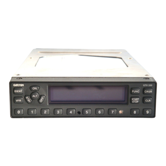
Figure 2-2 Unit Installation Considerations
GTX 330 Installation Manual
190-00207-02