- ページ 8
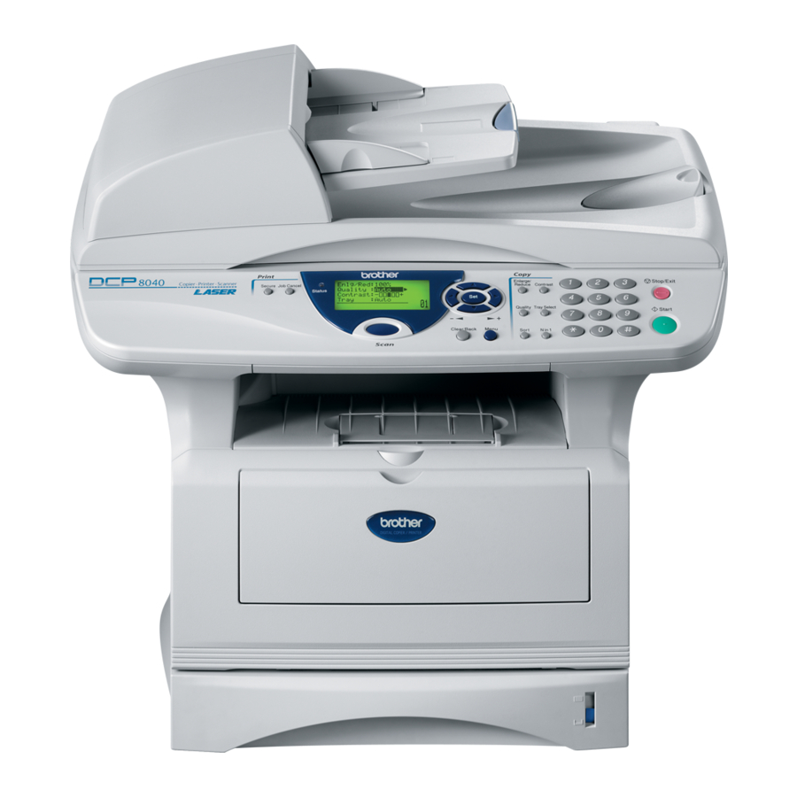
オール・イン・ワン・プリンター Brother DCP-8040のPDF サービスマニュアルをオンラインで閲覧またはダウンロードできます。Brother DCP-8040 12 ページ。 Digital copier & laser printer
Brother DCP-8040 にも: パンフレット&スペック (2 ページ), 部品リファレンスリスト (36 ページ), クイック・セットアップ・マニュアル (48 ページ), パンフレット&スペック (4 ページ)

3.11 Fine Adjustment of Scan Start/End Positions (Maintenance mode 54).......................... 7-18
3.12 CCD Scanner Area Setting (Maintenance mode 55) ..................................................... 7-20
3.13 EEPROM Customizing (Maintenance mode 74) ............................................................ 7-21
3.14 Printing out of Machine Log Information (Maintenance mode 77).................................. 7-22
3.15 Display of the Equipment's Log Information (Maintenance mode 80)............................ 7-24
3.16 Machine Error Code Indication (Maintenance mode 82) ................................................ 7-26
3.17 Output of Transmission Log to the Telephone Line (Maintenance mode 87) ................ 7-26
3.18 Cancellation of the Memory Security Mode (Not applicable to the Japanese version) . 7-27
APPENDIX 1 EEPROM CUSTOMIZING CODES ...................................A-1
APPENDIX 2 INSTALLING THE UPDATE DATA....................................A-3
1.
INSTALLING THE UPDATE DATA TO THE MACHINE.......................................... A-3
1.1
1.2
1.3
2.
SETTING ID CODES TO MACHINES..................................................................... A-5
2.1
2.2
2.3
APPENDIX 3 FIRMWARE SWITCHS (WSW) .........................................A-7
APPENDIX 4 CIRCUIT DIAGRAMS
4.1
4.2
4.3
4.4
4.5
4.6
4.7
4.8
4.9
4.10 Engine PCB Circuit Diagram (2/2)..................................................................................A-59
4.11 NCU PCB Circuit Diagram (U.S.A.)................................................................................A-60
4.12 NCU PCB Circuit Diagram (Europe) ..............................................................................A-61
4.13 NCU PCB Circuit Diagram (Asia) ...................................................................................A-62
4.14 NCU PCB Circuit Diagram (Oceania).............................................................................A-63
4.15 Control Panel PCB Circuit Diagram................................................................................A-64
4.16 Low-voltage Power Supply PCB Circuit Diagram (200V) ...............................................A-65
4.17 Low-voltage Power Supply PCB Circuit Diagram (100V) ...............................................A-66
4.18 High-voltage Power Supply PCB Circuit Diagram (200V) ..............................................A-67
4.19 High-voltage Power Supply PCB Circuit Diagram (100V) ..............................................A-68
fineline6
Connecting the Machine to Your PC ................................................................................A-3
Setting up the Machine and Your PC ...............................................................................A-3
Installing the Update Data onto the Flash ROM of the Machine ......................................A-4
Connecting the Machine to Your PC ................................................................................A-5
Setting Up the Machine and Your PC...............................................................................A-5
Running the Setup Utility ..................................................................................................A-6
Main PCB Circuit Diagram (1/7) .....................................................................................A-50
Main PCB Circuit Diagram (2/7) .....................................................................................A-51
Main PCB Circuit Diagram (3/7) .....................................................................................A-52
Main PCB Circuit Diagram (4/7) .....................................................................................A-53
Main PCB Circuit Diagram (5/7) .....................................................................................A-54
Main PCB Circuit Diagram (6/7) .....................................................................................A-55
Main PCB Circuit Diagram (7/7) .....................................................................................A-56
Driver PCB Circuit Diagram ...........................................................................................A-57
Engine PCB Circuit Diagram (1/2)..................................................................................A-58
MFC-8440/8840D/8840DN, DCP-8040/8045D/8045DN
vii
SERVICE MANUAL
