- ページ 10
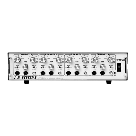
アンプ A-M Systems 1700のPDF マニュアルをオンラインで閲覧またはダウンロードできます。A-M Systems 1700 16 ページ。 Four-channel differential ac amplifier

Stimulus Mode
In Stimulus Mode, the
to apply the stimulation signal to the electrode. All amplification circuits are grounded in
this mode, and the
Record Mode
In Record Mode, the signal from the
a high impedance, low noise differential amplifier stage consisting of two operational
amplifiers with x10 gain. Direct coupling reduces the errors typically associated with
capacity input coupling. The operational amplifiers are in non-inverting mode and their
gain-setting networks connect through a common resistor to preserve high common-
mode rejection.
The common-mode voltage of the input signal at the inverting inputs of the operational
amplifiers is measured, and is used to drive the electrode cable shield. This improves
the common-mode rejection performance of the input amplifier stage. For this reason,
the driven shield should not be grounded.
The output signals are then connected to a second differential operational amplifier
circuit with a gain of x10. At this point, the differential electrode signal has been
amplified by x100 and converted to a single-ended signal with respect to ground. An
internal CMR potentiometer is trimmed at the factory to maximize the common-mode
rejection.
The signal passes through a double-pole low-pass filter, which attenuates frequencies
above the
HIGH CUT-OFF
If selected, the signal next passes through the Notch Filter. The Notch Filter is tuned
to the power line frequency and consists of a twin-T network in a feedback loop with an
operational amplifier. This stage does not amplify the signal.
The signal then passes through a double-pole high-pass filter, which attenuates
frequencies below the
the final amplifier which provides x1, x10 or x100 gain to produce an output signal
according to the total gain specified by the
A-M Systems
Theory of Operation
connector is connected internally to the
INPUT
connector is disabled.
OUTPUT
INPUT
switch setting. This stage provides no signal amplification.
switch setting. Also included in this stage is
LOW CUT-OFF
131 Business Park Loop, P.O. Box 850 Carlsborg, WA 98324
Telephone: 800-426-1306 * 360-683-8300 * FAX: 360-683-3525
E-mail: [email protected] * Website:
connector is coupled directly to the inputs of
switch.
GAIN
http://www.a-msystems.com
connector
STIMULUS
6
