- ページ 5
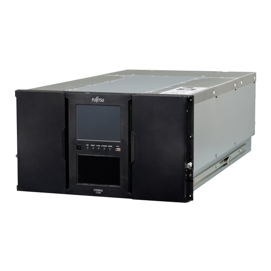
ストレージ Fujitsu ETERNUS LT260のPDF クイック・スタート・マニュアルをオンラインで閲覧またはダウンロードできます。Fujitsu ETERNUS LT260 5 ページ。 Tape library
Fujitsu ETERNUS LT260 にも: ユーザーマニュアル (44 ページ)

Speaker script
ETE-LT260-INM-WBT 02/03/2016
Push the Chassis Fan in its place and tighten using the thumbscrews.
After reconnecting the power cables switch on the LT260, ensure that the library accomplishes the initialization phase and reaches normal
operating status.
As a reminder, like always after a maintenance procedure, firstly verify that the fault status of the replaced component - and the related
components, like the Drives in the case of defective Drive Power Board - has been mended. Secondly, delete the related fault event or events
from the Event Log.
14. Removing and replacing Robotic Assembly
Because the following procedure requires the Base Module and Expansion Module to be detached from each other, it is very important that the
robotic assembly is in its parking position behind the OCP.
As a preparation for removing the Robotic Assembly all cables from both the Base Assembly and Expansion Module have been removed and
the two Modules are detached from each other by having moved the alignment pin in the upper position.
Always before extending a unit from a rack make sure the necessary measures are taken to prevent the rack from tilting.
Extend the Base Module fully from the rack so that you have access to the top cover.
Then remove the top cover by pressing down the locking catch and at the same time moving the cover towards the front of the library.
Slide the cartridge carrier toward the center of the robotic assembly to access the robotic locking lever.
Move the blue locking lever first to left, then towards the front of the library and then to the right.
Now pull up very slowly - not more than about one centimeter per second - the robotic assembly upwards.
Very carefully lift the assembly out of its moving mechanism not to damage the spooling cable attached to it.
Place the mechanism on top of the Base Module while observing the spooling cable not being damaged.
Detach the cable from the assembly using a small flat head screwdriver.
Before installing the Robotic Assembly ensure that the blue locking pin is in unlocked position.
As the first step reconnect the spooling cable and then use any of the four gears at the corners of the robotic assembly to align the pins
horizontally.
Place the Robotic Assembly at the top of the moving mechanism and let the assembly sink downwards - it does not sink by itself then you may
have to push it slightly to make it move downwards. Let the Robotic Assembly fall until it resides approximately in the parking position behind
the OCP.
Now turn the blue locking lever to locked position.
Now you can replace the top cover, push both Modules back in the rack and align them accordingly, connect all cables and switch the library
power on.
Make sure the LT260 establishes normal operating mode.
15. Replacement of the Spooling Cable
Before being able to replace the Spooling Cable the Robotic Assembly needs to be removed, please refer to the respective video clip.
In order to have access to the Spooling Cable the left side Magazine needs to be pulled out. As the library is at the moment switched off it is
naturally not possible to release the Magazine using the respective menu option, instead a mechanical release lever needs to be applied.
This can be found about in the middle of the magazine, between the door and the magazine.
Push the lever and simultaneously extend the magazine out from the library chassis.
To remove the Spooling Magazine it is necessary to release its locking lever while lifting it upwards.
Replacement is very simple by sliding the cable assembly to its place until the locking lever snaps on.
Rest of the procedure is the same as when replacing the Robotic Assembly; please refer to the respective video clip.
16. Replacement of the OCP
For replacing the OCP the library must naturally be switched off.
After opening the magazine access doors, use a small screwdriver or similar and place it in the hole on the top side of the OCP. Push gently to
loosen the release catch and pull the corner of the OCP slightly outwards. Repeat with the other corner of the OCP.
While carefully tilting and lifting the OCP, pull it outwards to have access to the connection cable and release it from its connector.
When installing the OCP, connect first the cable and before pushing the OCP in its place make sure the cable is correctly routed in the channel
behind the clear plastic window.
Replacement of the front panel of the Expansion Module follows the same procedure, but naturally without the OCP cable.
Switch on the library, before the normal initialization phase starts it is necessary to calibrate the touchscreen, for that follow the instructions on
the screen.
Consequently, make sure the LT260 establishes normal operating mode.
Page 5 of 5
Fujitsu Training Academy
