- ページ 4
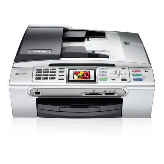
ソフトウェア Brother MFC-440CNのPDF サービスマニュアルをオンラインで閲覧またはダウンロードできます。Brother MFC-440CN 5 ページ。 Quick setup guide - english
Brother MFC-440CN にも: クイック・セットアップ・マニュアル (34 ページ), セットアップマニュアル (23 ページ), クイック・セットアップ・マニュアル (35 ページ), サービスマニュアル (17 ページ)

How this manual is organized
This manual is made up of nine chapters and appendices.
CHAPTER 1
PARTS NAMES AND FUNCTIONS
Contains external views and names of components and describes their functions. Information about
the keys on the control panel is included to help you check operation or make adjustments.
CHAPTER 2
SPECIFICATIONS
Lists the specifications of each model, which enables you to make a comparison of different models.
CHAPTER 3
THEORY OF OPERATION
Gives an overview of the scanning and printing mechanisms as well as the sensors, actuators, and
control electronics. It aids in understanding the basic principles of operation as well as locating
defects for troubleshooting.
CHAPTER 4
ERROR INDICATION AND TROUBLESHOOTING
Details error messages and codes that the incorporated self-diagnostic functions display if any error
or malfunction occurs. If any error message appears, refer to this chapter to find which components
should be checked or replaced.
The latter half of this chapter provides sample problems that could occur in the main sections of the
machine and related troubleshooting procedures. This will help service personnel pinpoint and
repair defective components.
CHAPTER 5
TRANSFER OF DATA LEFT IN THE MACHINE TO BE SENT FOR REPAIR
Describes how to transfer data left in the machine to be sent for repair. The service personnel
should instruct end users to follow the transfer procedure given in this chapter if the machine at the
user site cannot print received data due to the printing mechanism defective. End users can transfer
received data to another machine to prevent data loss.
CHAPTER 6
DISASSEMBLY/REASSEMBLY AND LUBRICATION
Details procedures for disassembling and reassembling the machine together with related notes. The
disassembly order flow provided enables you to see at a glance the quickest way to get to
component(s) involved.
At the start of a disassembly job, you check the disassembly order flow that guides you through a
shortcut to the target components.
This chapter also covers screw tightening torques and lubrication points to which the specified
lubricants should be applied during reassembly jobs.
CHAPTER 7
ADJUSTMENTS AND UPDATING OF SETTINGS, REQUIRED AFTER PARTS
REPLACEMENT
Details adjustments and updating of settings, which are required if the head/carriage unit, main PCB
and some other parts have been replaced.
CHAPTER 8
CLEANING
Provides cleaning procedures not covered by the User's Guide. Before starting any repair work,
clean the machine as it may solve the problem concerned.
ii
Confidential
