- ページ 6
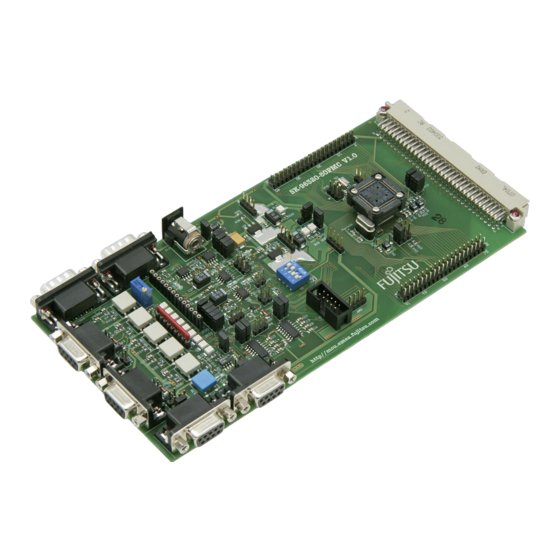
マザーボード Fujitsu F2MC-16FX QFP-100PのPDF 操作マニュアルをオンラインで閲覧またはダウンロードできます。Fujitsu F2MC-16FX QFP-100P 14 ページ。 For dsu-fr emulator
Fujitsu F2MC-16FX QFP-100P にも: ユーザーマニュアル (34 ページ)

■ MCU footprint design notes
Figure 2 shows the recommended dimensions of the footprint for mounting the NQPACK on the
printed circuit board of the user system.
The printed circuit board of the user system must be designed with due consideration given to this
footprint as well as to the mass production MCU.
For more information, contact Tokyo Eletech Corporation.
*1 : The positions of the holes (φ1.0) for the guide pins when the NQPACK is mounted.
*2 : The position of the screw hole (φ3.2) used to affix the IC socket when the
Figure 2 Recommended dimensions of the footprint for mounting the NQPACK
■ Notes on the sub clock
When using this product, it is not possible to supply the sub clock from the user system to the eval-
uation MCU. If the evaluation MCU operates using the sub clock, use the sub clock on the adapter
board.
See the operation manual for the adapter board for details.
0.65mm × 19 = 12.35mm
0.65mm
φ3.2mm*
2.4mm
These holes are not needed if the guide pins are not used.
NQPACK100RB179-SL-A (Tokyo Eletech Corporation, sold separately) is mount-
ed. This hole is not needed if the NQPACK100RB179-SL-A is not used.
0.35mm
2
3-φ1.0mm*
1
6.0mm
13.8mm
2.4mm
No. 1 pin
3
