- ページ 2
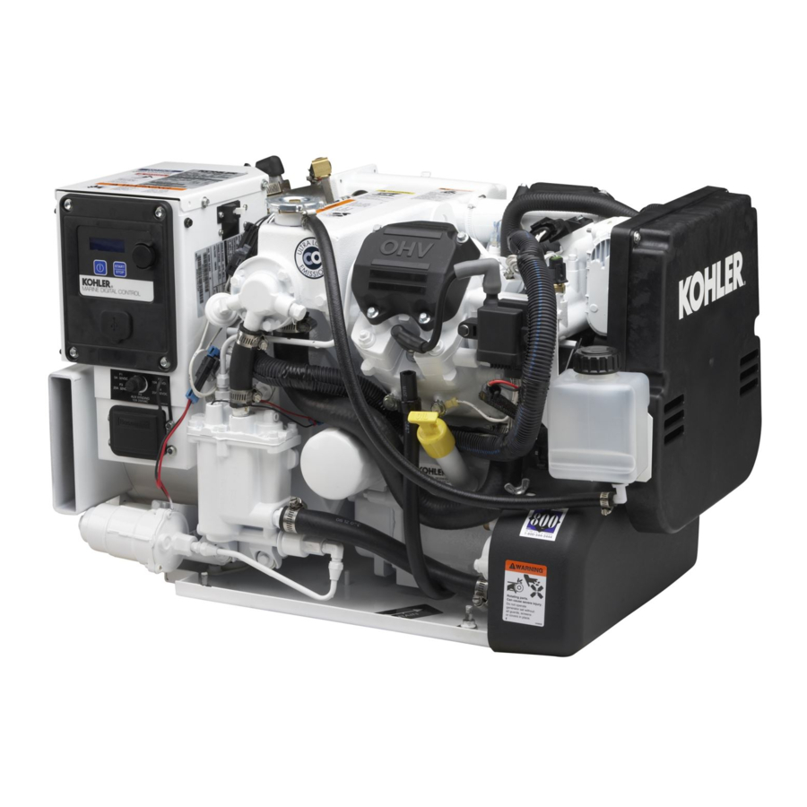
配管製品 Kohler 23EOZDのPDF インストレーション・インストラクションをオンラインで閲覧またはダウンロードできます。Kohler 23EOZD 2 ページ。 Marine seawater pump service kit gm59333

2.
Remove and replace the seawater pump.
2.1
Remove and save the belt guard.
2.2
Remove and save the seawater pump belt. See
Figure 1.
2.3
Remove and discard the existing seawater pump,
mounting bracket, and seawater pump hardware.
Engine-End View
3
2
1
1. Seawater pump (344089)
2. Mounting bracket
3. Seawater pump belt
Figure 1 Locator Drawing (Typical)
2.4
Mount the seawater pump (GM46936) to the new
bracket (GM53017) using 2 bolts (X-125-31) and
2 nuts (X-6210-7) as shown in Figure 2.
2.5
Mount the new bracket/pump assembly to the
engine using the hardware shown in Figure 2.
2.6
Replace the seawater pump belt. Consult the
operation
manual
procedure.
2.7
Attach the pipe adapters to the seawater pump
and cut to fit the hose attached to the bottom of the
seawater pump. See Figure 2.
2.8
Replace the belt guard.
3.
Restore the generator set to service.
3.1
Check that the generator master switch is in the
OFF position.
3.2
Reconnect the generator set engine starting
battery, negative (−) lead last.
3.3
Reconnect the power to the battery charger, if
equipped.
2
DK-250000-AI
for
the
belt
tensioning
(Shown with belt guard removed.)
5
Side View
4
3
2
1
1. Bolt (X-125-31 qty. 2) and nut (X-6210-7 qty. 2)
2. Pipe adapter (GM58848) and 90_ connector (X-391-31)
3. Seawater pump (GM46936)
4. Pipe adapter (GM58848) and hose connector (X-582-16)
5. Screw (M931-08070-60), washer (M125A-08-80), and nut
(M6923-08-80)
6. Use existing hardware and spacers (X-400-74 qty. 2) behind
bracket as required.
7. Mounting bracket (GM53017)
8. Screw (M931-08100-60), washer (M125A-08-80) and spacer
(X-400-74). Locate spacer between bracket and gear cover.
Figure 2 Seawater Pump Installation
Parts List
Seawater Pump Kit GM59333
Qty. Description
1
Pump, seawater
2
Bolt (5/16-18 x 0.875 in.)
2
Nut, flanged (5/16-18 in.)
1
Bracket, mounting
2
Adapter, pipe
2
Washer, plain (8.4 mm ID x 16 mm OD) M125A-08-80
1
Nut, hex (8 mm)
1
Screw, hex cap (M8 x 70 mm)
1
Screw, hex cap (M8 x 100 mm)
1
Connector, 90_
3
Spacer (0.344 ID x 0.625 OD x 0.25 in.) X-400-74
1
Connector, hose
Engine-End View
6
7
8
GM59220-D
Part Number
GM46936
X-125-31
X-6210-7
GM53017
GM58848
M6923-08-80
M931-08070-60
M931-08100-60
X-391-31
X-582-16
TT-1479
11/10
