- ページ 4
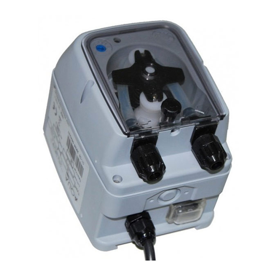
水ポンプ Aqua TEC-RSのPDF 取扱説明書をオンラインで閲覧またはダウンロードできます。Aqua TEC-RS 20 ページ。 Peristaltic pump

ENGLISH
Speed adjustable peristaltic pump
Power supply: read the label on the pump
Absorbed power (max): 4 W.
Suction height (max): 1.5 m.
Capacity and backpressure: read the label on the pump
Before starting the assembly, read carefully these instructions and follow them when installing.
Should the instructions indicated in this manual be not observed or not followed correctly, damages to
people, device and/or the system may occur.
Our pumps are manufactured according to General Standards in force and in compliance with the following
European Directives:
n° 2004/108/CE " e s.m.i.
n° 2006/95/CE "DBT Low Voltage Directive" e s.m.i.
n° 2011/65/UE , 2012/19/UE "direttive RoHs e WEEE" e s.m.i.
It is recommended to read carefully the label located on the pump and verify the following sections:
The peristaltic tube must be compatible with the liquid to be dosed.
Power voltage must be compatible with that indicated.
Pressure in correspondence to the injection section must be lower or equal to the nominal one of the pump.
Use the provided adhesive label to fix the pump to the wall.
Apply the label on the wall, where the pump must be placed, and drill holes in the two sections of the adhesive card.
Fix the bracket to the wall using the provided plugs and screws.
Place the pump on the bracket.
Ensure the fixing is stable.
It is also recommended to install the pump in a dry environment, away from heat sources and exhaust
vapour.
Before performing any intervention on the pump, disconnect the power supply voltage of the machine.
Connect the cable of the pump at a voltage compatible with the label one, so that there can be an all-pole disconnection
device with a contact opening distance of at least 3 mm.
CAUTION !!!!!
Verify that the earth system is perfectly functional and complies with the applicable regulations. Make
sure that the highly sensitive differential switch is present (0.03 A). Verify that the rated values of the
pump are compatible with those of the mains. Never install the pump directly in parallel with inductive
loads (e.g. motors/solenoid valves) if necessary, use an isolating relay.
There are 2 protection devices inside the pump: a varistor and a fuse.
the suction tube must be located inside the product container and then connected to the pump suction fitting (with ▲
mark on the cover) and tightened with the appropriate ring-nut.
the delivery tube must be inserted on the pump delivery fitting (with ▼ mark on the cover) and tightened with the
appropriate ring-nut; then connect it to the tank inlet fitting or to the injection valve.
Drill a hole of 10 mm and insert the inlet fitting in the tank.
Connect the injection valve between the solenoid valve and the boiler of the washing machine. The provided tube holder
fitting can also be used to connect the valve directly to the hydraulic doser tube.
The potentiometer allows to adjust the pump speed:
to the minimum (totally counter clockwise rotated): 10%
to the maximum (totally clockwise rotated): 100%
Moreover, speed is displayed by modulating the green LED period on the basis of 10 seconds.
The two-coloured Led indicates the various pump operation phases:
if it is fixed orange, the pump is performing the priming phase.
if it is flashing green, the pump operates regularly; moreover, the flashing frequency is directly proportional to the
speed rotation, in fact:
10% => 5 seconds on and 5 seconds off – in 10 seconds it performs 1 flash (slow)
50% => 1 second on and 1 second off – in 10 seconds it performs 5 flashes
100% => 0.5 seconds on and 0.5 seconds off – in 10 seconds it performs 10 flashes (fast)
flashing red means the motor is blocked or, in the level probe version, it indicates the exhaustion of the chemical
product to be dosed.
fixed red means the pump is in stand-by, switch positioned on off or the pump is performing the three re-starting
attempts of the motor.
06/08/2014
TECHNICAL FEATURES
STANDARDS OF REFERENCE
BEFORE STARTING
WALL MOUNTING
ELECTRIC INSTALLATION
HYDRAULIC INSTALLATION
TANK INLET ASSEMBLY (see fig. 1)
INJECTION VALVE ASSEMBLY (see fig. 1)
OPERATION OF THE PUMP (see. fig. 2)
OPERATION OF THE TWO-COLOURED LED
ADSP7000199I Rev. 1.5
4
