- ページ 5
アンテナ A.H. Systems AK-40GのPDF 操作マニュアルをオンラインで閲覧またはダウンロードできます。A.H. Systems AK-40G 20 ページ。 Antenna kit

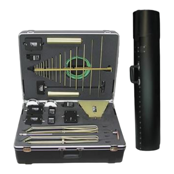
A.H. Systems AK-40G Antenna Kit
SPECIFICATIONS
GENERAL DESCRIPTION
The A.H. Systems AK-40G antenna kit series consist of five E-field antennas,
one magnetic loop antenna, and two current probes. Each of the antennas and
probes are provided with calibrations when connected to a 50-ohm input
receiver or spectrum analyzer.
Each of the E-field antennas mount directly to the tripod azimuth and elevation
head. The azimuth and elevation head allows the operator to vary the antenna
azimuth (direction) and to change the antenna polarity (vertical or horizontal).
Cables and an adapter are provided to connect each antenna and probe to
either a BNC or N type connector on the receiver. Cable calibrations are
supplied.
To obtain the field strength of the signal being measured, the operator must add
the receiver reading in dBuV, the antenna factor in dB, and the cable
attenuation in dB. This yields the field strength in dBuV/m. Calibrations for the
E-field antennas are supplied at appropriate spacings (1, 3, and 10 meter) to
comply with various specification requirements.
ANTENNA SPECIFICATIONS
SAS-510-2 Log Periodic Antenna specifications:
SAS-542 Biconical Antenna specifications:
© A.H. Systems inc. – REV C
Frequency Range ........................................................................... 290 MHz – 2 GHz
Antenna Factor ....................................................................................... 14 to 32 dB/m
Antenna Gain ..................................................................................................... 6.5 dBi
Maximum Continuous Power ...................................................................... 1000 Watts
Average Beamwidth ................................................................................................. 45°
Average Beamwidth (H-Field) ................................................................................ 100°
Impedance (nominal) ............................................................................................. 50
Average VSWR ........................................................................... 1.45:1 typ. 2.2:1 max
Maximum Radiated Field ................................................................................. 200 V/m
Connector ........................................................................................... N-Type (female)
Mounting ............................................................................................... 1/4-20 (female)
Weight ................................................................................................. 1.4 lbs.
Size (L x W x H) ....................................... 22.5" x 20.1" x 2.5" (
Frequency Range ......................................................................... 20 MHz – 330 MHz
Antenna Factor ...................................................................................... 8.5 to 21 dB/m
Antenna Gain ........................................................................................... -22 to 2.8 dBi
Impedance (nominal) ............................................................................................. 50
Average VSWR .............................................................................................. 2.0:1 typ.
Maximum Continuous Power ............................................................................ 1 Watts
Connector ........................................................................................... N-Type (female)
Mounting ............................................................................................... 1/4-20 (female)
Weight ................................................................................................. 4.3 lbs.
Size (W x H) .................................................................... 52.75" x 29"
(0.64 kg)
57.2 cm x 51cm x 6.3cm)
(1.95 kg)
(134cm x 73.7cm)
5
