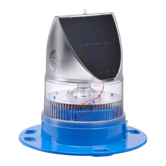
- ページ 8
GPS Avlite AV-70のPDF マニュアルをオンラインで閲覧またはダウンロードできます。Avlite AV-70 16 ページ。 Aviation light
Avlite AV-70 にも: クイック・スタート・マニュアル (2 ページ)

3 Assembly & Installation
The installation of the AV70 Solar Airfield Light includes the following steps:-
• Unpacking
• Initial Inspection
• Assembling the light
• Installing the light assembly
Assembly & Installation of the AV70 with Rubber Tile
3.1
Tools required
• Large flat blade screwdriver (to suit "Flash Adjustment" bung)
• Hammer
3.1.1
Unpacking instructions
Unpack all hardware and verify container contents in accordance with Figure 3 below. Please contact your
Avlite office if there is any hardware missing.
3.1.2
Initial inspection
Inspect all hardware for damage. If there is any damage, please contact your Avlite Office. Retain original
packing material for possible future use in shipping the AV70.
3.1.3
Assembly
Refer to Figure 3 "General Arrangement of AV70 and Rubber Tile" during assembly and installation of the light.
3.1.3.1 Assembling the light
a. Use a large flat-blade screwdriver to remove the Flash Adjustment bung from the base of the light
(see Figure 2).
A sealed vent on the base allows air transfer without moisture intake and should not be disturbed.
b. Set the toggle switch, which is visible just inside the bung hole, to the "ON" position. This will
activate the AV70.
Intensity and flash settings are factory set using DIP switches and rotary switches next to the
toggle switch. These should not be altered.
c. To test operation of the light, place a dark cover (towel or jacket) on top of the light to activate the
sensor. The light should come on within about 60 seconds.
d. Replace the Flash Adjustment bung.
Latest products and information available at
8
www.avlite.com
AV70 Solar Airfield Light
