- ページ 3
コントロールユニット Avnet MSC C6B-KLH-7102E-NN0201CのPDF 取付方法をオンラインで閲覧またはダウンロードできます。Avnet MSC C6B-KLH-7102E-NN0201C 4 ページ。 Com express basic module. heat spreader

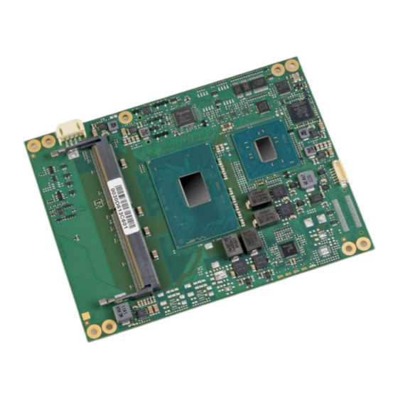
MSC C6B-SLH / KLH / CFLH / CFLR
Heat spreader mounting instructions
1 Introduction
This document is designed to give the customer a better understanding of important considerations, when
using MSC heat spreaders on the MSC C6B-SLH, MSC C6B-KLH, MSC C6B-CFLH or MSC C6B-CFLR
module. Below you will find important guidelines that must be followed to ensure that the heat spreader is
properly mounted.
1.1
General Information
Modern computers use very dense chip architectures that create a lot of heat in a relatively small area. To
make sure that the parts are used within their specifications, it is necessary to provide a method to
conduct the thermal energy away from the sensitive semiconductor dies. For this purpose MSC offers
different cooling solutions, a heat spreader and a heat spreader.
Note: This heat-spreader by itself does not constitute the complete thermal solution for a COM Express
Module, but provides a common interface between modules and implementation-specific thermal
solutions.
2 Mounting Instructions
Photo 1 shows the heat spreader bottom side. It is delivered in a blister packaging together with some
screws that are used to fix the heat spreader onto the C6B-SLH/KLH/CFLH/CFLR module. The frame
shows the thermal contact locations of the heat spreader. According to the amount of heat, that has to be
transferred, different materials have to be chosen to achieve optimal thermal contact. The grey pad
consists of a phase change material that melts the first time it is heated. Due to the mechanical pressure
between die and heat spreader, the residual material is pressed out of the gap; thus leaving behind only a
very thin film with a very good thermal performance. Since this pad is printed on the aluminium, it is very
soft and sensitive to scratches. If you happen to damage the surface of the pad, use a clean knife or
something similar and try to reshape it so that the die surfaces are completely covered.
The blue pad under the smaller ALU block is designed not only to conduct the heat but also to
compensate for mechanical tolerances between chipset and heat spreader.
Photo 1: Heat spreader bottom side
3 / 4
