- ページ 10
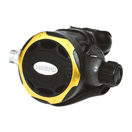
コントローラー Aqua Lung Legend LX Second StageのPDF テクニカル・メンテナンス・マニュアルをオンラインで閲覧またはダウンロードできます。Aqua Lung Legend LX Second Stage 18 ページ。

10
21.
Perform the venturi test:
a.
To test the venturi control, place the lever in the
plus position.
b.
Depress the purge cover. You should get loud, run
away freeflow.
c.
While the regulator is freeflowing, move the venturi
lever to the minus position. The freeflow should
stop abruptly. If it doesn't stop abruptly, the crown
orifice may be out too far. Try turning it in (clock-
wise) 1/8 of a turn and try again.
Set to "+" and purge
22.
Turn off the air supply and purge the second-stage by
pressing on the lever. Pull back on the adjustment wheel
and unscrew the inline tool from the second-stage.
Remove the hose from the inline tool.
23.
Attach the hose to the second stage. While holding the
retaining nut (15) with a ¹¹₁₆" wrench, tighten the hose
swivel to a torque value of 40±2 inch-lbs.
F
NOTE: If your facility is equipped with a test
bench, perform the tests before installing the
mouthpiece. General instructions for performing
bench tests are located in the next section, "Final
Testing."
25.
If equipped with a Comfo-bite mouthpiece, make sure
the 'bridge' of the mouthpiece (12) is facing upward.
Stretch the mouthpiece over the second-stage mouth-
piece boss. At the base of the mouthpiece is a groove
for the reusable clamp (10). Wrap the clamp around the
mouthpiece so that the cam buckle points toward the
hose and the cam lever points downward. Mate the cam
lever hook with the hook on the free end of the clamp.
Press down on the cam lever until the buckle snaps
closed.
26.
If the regulator is a Supreme model, install the lip shield
(9) by stretching it over the mouthpiece and pressing it
up against the reusable clamp.
FINAL TESTING
Second Stage Opening Effort Test
1.
Connect the first stage regulator to a calibrated test
bench and pressurize the system to 3000 (±100) psi.
Slowly open the flowmeter control knob (start vacuum)
while watching both the magnahelic gauge and the
intermediate pressure gauge.
2.
When the intermediate pressure begins to drop, indicat-
ing the second-stage valve is open, the magnahelic
gauge should indicate an opening effort of +0.8" to +1.4"
Move to "-" to stop flow
Legend LX Second Stage Service Manual
of H
O for a standard 2nd-stage, or +1.1" to +1.7" of
2
H
O for the supreme 2nd-stage. If the reading exceeds
2
these specifications, refer to refer to "Table 1 - Trouble-
shooting" for corrective actions.
Second Stage Air Flow Test
1.
Slowly turn the flowmeter control knob until the flow
reaches a minimum of 15 SCFM (425 liters per minute).
The reading on the Magnahelic gauge (inhalation / exha-
lation effort gauge) should indicate no more than +6.O"
H2O. If the reading exceeds +6.0" H2O, refer to refer to
"Table 1 - Troubleshooting" for corrective actions.
Second Stage Purge Flow Test
1.
Turn off the flowmeter control knob. Next, while the sec-
ond stage is still mounted on the mouthpiece adapter,
watch the flowmeter gauge and depress the purge
button until the second stage valve is completely open.
The flowmeter gauge must indicate a minimum of +10.0
SCFM (284 Liters per minute.). If the purge flow is less
than +10.0 SCFM, refer to "Table 1 - Troubleshooting."
2.
When purge flow is correct, remove the second-stage
from the mouthpiece adapter on the flow test bench.
Shut the valve of the test bench, and purge the second
stage to depressurize the system. Remove the regula-
tor.
External Leak Test
1.
After disconnecting the regulator from the flow bench,
connect it to a scuba cylinder filled to approximately
3,000 psi. Open the cylinder valve to repressurize the
regulator, and submerge the entire system in a test tank
of clean water.
2.
Observe any bubbles arising from the submerged regu-
lator over a one minute period. The recommended time
is necessary due to slower bubble formation that occurs
in smaller leaks. Bubbles indicate a leak, which requires
that the system must be disassembled at the source to
check sealing surfaces, assembly sequence and compo-
nent positioning in order to correct the problem(s).
F
NOTE:
Extremely small leaks may be better
detected by applying a soap solution or Snoop™
to the leak area. Bubble streams will indicate
the source of the leak. Before disassembling to
correct any leaks, rinse the entire regulator thor-
oughly with fresh water and blow out all residual
moisture with filtered, low-pressure (50 psi) air.
Disassemble and remedy the problem, referring
to "Table 1 - Troubleshooting."
Subjective Breathing Test
1.
Depress the purge cover fully to ensure that an ad-
equate volume of air needed to clear the second stage
flows through the mouthpiece. Then, inhale slowly but
deeply from the mouthpiece. A properly serviced and
adjusted regulator should deliver air upon deep inhala-
