- ページ 3
スイッチ ABACOM Technologies RF-LPSのPDF クイック・スタート・マニュアルをオンラインで閲覧またはダウンロードできます。ABACOM Technologies RF-LPS 4 ページ。 Low power rf controlled switch

RF-LPS Specifications
Absolute Limits and Operating Parameters
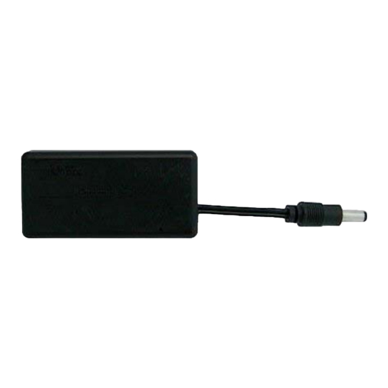
Input/Output DC Connector
Breakdown Voltage
Max. Current Throughput
Receiver Frequency
Receiver Sensitivity
Receiver Front-end Filter
Modulation
Receiver Architecture
Replacement Batteries
Number of selectable addresses
RF-LPS when used with TX12E-2C Keyfob Transmitter
This section applies only to the RF-LPS and TX12E-2C transmitter.
The TX12E-2C has two sets of DIP switches internally:
•
One 10 position DIP switch and
•
One 4 position DIP switch
10 Position DIP switch
Switches 1-8 are for configuring the system address. These settings may be any combination provided
they are the same settings for both the transmitter and the receiver.
Switch position 9 must always be set to OFF. (default position). This is important for correct operation.
Switch 10 position will affect the output state of D3 pin header on the RF-LPS.
DIP switch 10 in the OFF position (default position) will always result in a HIGH state on pin D3 regard-
less of which button is keyed on the transmitter. Conversely, with DIP switch 10 in the ON position will
always result in a LOW state on pin D3 regardless of which button is keyed on the transmitter.
4 Position DIP switch
DIP switch 2 must ALWAYS be set to ON
DIP switch 4 must ALWAYS be set to OFF (set to OFF by default. Do not change)
DIP switches 1 and 3 may be set to the combinations according to the truth table on the next page:
ABACOM Technologies, Inc.
Button 2
Button 1
(set to ON by default. Do not change)
•
383 Bering Ave • Etobicoke • ON • M8Z 3B1 • Tel +1(416)236-3858 • Fax +1(416)236-8866
www.abacom-tech.com
2.1mm Center Positive
5V to 35V
200mA
433.92MHz
-94dBm
600KHz
AM
Super Regenerative
3V Lithium Ion 2450 series
255
4 position DIP switch
10 position DIP switch
