- ページ 2
マザーボード DFRobot X-Board V2のPDF マニュアルをオンラインで閲覧またはダウンロードできます。DFRobot X-Board V2 3 ページ。

Specifications
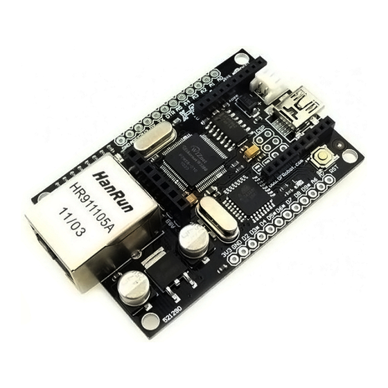
MCU: Atmega328P low voltage version (16Mhz)
Ethernet: WIZ 5100
Arduino Uno bootloader
Supply voltage:5~12v
Output voltage:5v/3.3v
Digital IO: 8
Analog In: 8
Envionment Friendly: Rohs Compliance
Informational LED
PWR: indicates that the board and shield are powered
LINK: indicates the presence of a network link and flashes when the shield transmits or receives data
FULLD: indicates that the network connection is full duplex
100M: indicates the presence of a 100 Mb/s network connection (as opposed to 10 Mb/s)
RX: flashes when the shield receives data
TX: flashes when the shield sends data
COLL: flashes when network collisions are detected
Xboard V2 Pinout Diagram
Connection Diagram
This connection diagram shows how to connect the FTDI programmer to the X-board for uploading an Arduino
sketch.
NOTE: Please select "arduino UNO" from the boards list in the Arduino IDE.
