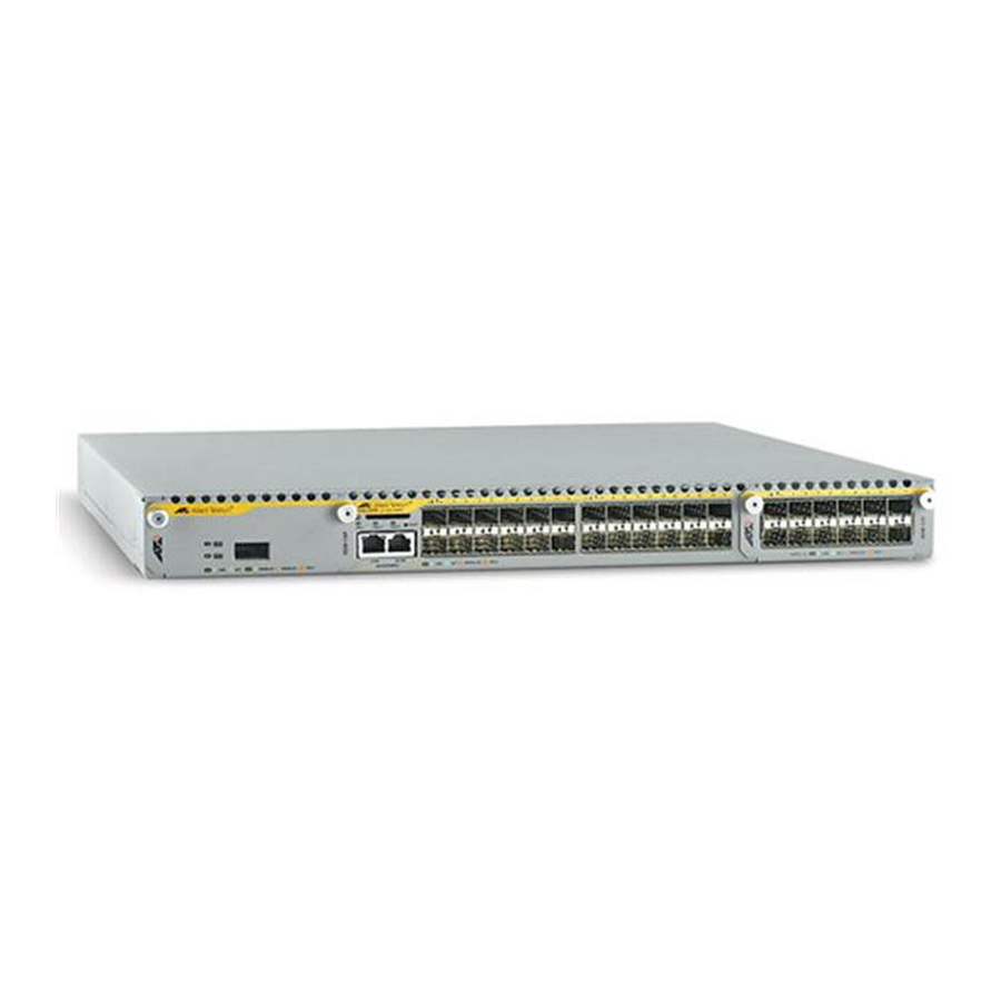
- ページ 9
ネットワーク・ルーター Allied Telesis x900 SeriesのPDF インストレーション・マニュアルをオンラインで閲覧またはダウンロードできます。Allied Telesis x900 Series 13 ページ。 Removable power supply and fan
Allied Telesis x900 Series にも: 設定方法 (9 ページ)

8.
Ensure the circuit breaker for the supply circuit and the Run/Standby
control on the PSU are off. Use a small diameter pin to press and release
the Run/Standby control so that it is not pushed in (which is the Off
position).
9.
Connect the supply cable wires to the circuit breaker.
10. Turn on the PSU by pushing in the Run/Standby control with a small
diameter pin.
Checking LEDs
LEDs indicate the operational status on the faceplate of each PSU and on the
front panel of the switch.
After you have inserted the PSU and powered on the switch, check the LEDs for
correct operation by using the following tables.
Table 1: LEDs on the power supply unit and fan-only module
LED
State
Fault
Red
PWR
Green
Description
The temperature of the PSU has exceeded the limit of
º
75º C (167
F), or the FOM has failed.
A PSU is installed in the switch and is receiving power.
FOMs do not have this LED.
Installation Guide
9
