- ページ 2
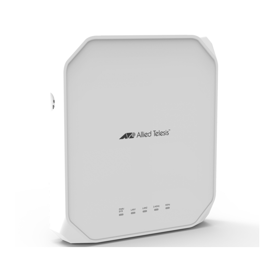
無線アクセスポイント Allied Telesis AT-TQ6702 GEN2-RのPDF クイック・インストール・マニュアルをオンラインで閲覧またはダウンロードできます。Allied Telesis AT-TQ6702 GEN2-R 4 ページ。

Installing the Mounting Bracket on a Wall or Ceiling
1.
Choose a location and orientation for the access point on the wall or ceiling.
2.
Position the mounting bracket at the selected location for the access point. With a
pencil, mark the two key-hole slots on the wall or ceiling.
3.
If necessary, pre-drill on the wall or ceiling the two marked locations of the key-hole
slots for the screws.
4.
Install two M4 screws and anchors (if required) into the wall or ceiling. Leave the
screws loose enough so that you can slide the bracket under the screw heads.
For wooden walls or ceiling, Allied Telesis recommends M4 25 mm flat-head wood
screws and anchors (if required). The screws and anchors are not provided.
5.
Install the openings of the bracket key-hole slots to the two screw heads and slide
the bracket into the narrow end of the key-hole slot openings.
6.
Tighten the screws snugly onto the bracket.
7.
To secure the mounting bracket, pre-drill holes through the two bracket mounting
holes opposite the key-hole slots.
8.
Install and tighten two M4 screws (not provided).
Cabling the Wireless Access Point
Perform the following procedure to cable the Ethernet LAN port and to power the device:
1.
Connect an Ethernet cable to LAN1 (POE) port.
4
2.
Connect the other end of the Ethernet cable to a network device, such as a switch or
router.
Note
When LAN1 port is connected to PoE+ power sourcing equipment, the TQ6702
GEN2 access point powers on and begins to initialize its management software.
3.
To use LAN2 port in the static LAG or Cascade mode, connect a second Ethernet
cable to LAN2 port.
4.
Connect the other end of a network device.
To use LAN2 port as a static LAG with LAN1 port, connect LAN2 to the same switch
or router as LAN1 port. To use it in the Cascade mode, connect LAN2 to a different
device.
Note
The default setting for LAN2 port is disabled. To enable the port, use the web
management interface. For more details, see the TQ6702 GEN2 Management
Software User's Guide.
Note
Do not enable the LAN2 port until you have configured the other network device
for the static LAG.
Powering the Wireless Access Point
The access point can be powered with PoE+ on the LAN1 or/and LAN2 ports, an external
AC/DC power adapter, or both. The access point is powered by both PoE and an external
power adapter uses the adapter as its primary power and PoE as redundant power.
Allied Telesis recommends the PWRADP-01 (DA-48Z12) AC/DC Power Adapter. The
power adapter is ordered separately.
1.
Plug the DC connector into the DC IN jack on the access point.
2.
Connect the power adapter into an appropriate AC power source.
3.
Turn on the Power Switch on the panel.
Note
The power switch on the access point controls power from the AC power supply. It
does not control PoE+ on the LAN1 and LAN2 ports.
5
6
