- ページ 13
サーバー Dell PS4100のPDF ハードウェア・メンテナンス・マニュアルをオンラインで閲覧またはダウンロードできます。Dell PS4100 47 ページ。 Storage array
Dell PS4100 にも: ハードウェアマニュアル (50 ページ), 概要 (7 ページ), インストールとセットアップマニュアル (41 ページ), セッティング (2 ページ)

2 Maintaining Drives
You can replace a failed drive while the array remains running.
About Drive Types
Depending on your configuration, your array supports up to 24 2.5-inch SAS drives or up to 12 3.5-inch
SAS drives in internal drive bays.
Drives are connected to a backplane through drive carriers and are hot-swappable.
Drives are supplied in a carrier that is keyed to fit into specific array models, and cannot be installed in other
Dell arrays or arrays not from Dell Inc.
Identifying Failed Drives
A drive failure is indicated by:
• LEDs on the drive. See
• A message on the console, in the event log, or in the Group Manager Alarms panel.
• Indications in the Group Manager Member Disks window or the CLI
command output.
Behind the bezel, arrays have a label showing the drive numbering for that specific array model:
• In arrays with 2.5-inch drives (installed vertically in a row), the drives are numbered 0-23, left to right.
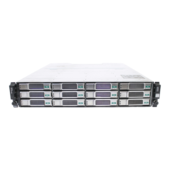
• In arrays with 3.5-inch drives (installed horizontally), the drives are numbered from left to right and top
to bottom, starting with 0 on the upper left side.
Table 3
shows the drive order for the 3.5-inch drives.
Interpreting Drive LEDs
The LEDs on a 3.5-inch drive are shown in
Drive LED states are described in
Interpreting Drive
LEDs.
Table 3 3.5-inch Drive Numbering
0
1
4
5
8 9 10 11
Figure
Table
4.
2
3
6
7
6. The LEDs on a 2.5-inch drive are shown in
member select show disks
Figure
7.
7
