- ページ 36
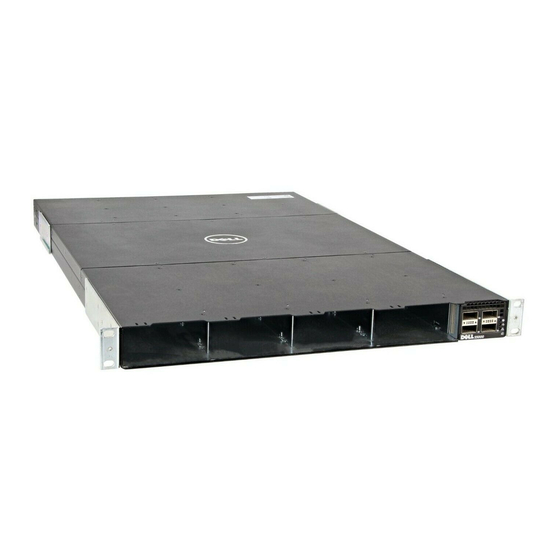
スイッチ Dell Networking S5000のPDF インストレーション・マニュアルをオンラインで閲覧またはダウンロードできます。Dell Networking S5000 50 ページ。 Data center switch
Dell Networking S5000 にも: 設定マニュアル (12 ページ), 設定マニュアル (17 ページ), スタートマニュアル (37 ページ)

NOTE: For better performance, ensure that the system is connected to a stand-alone power source with stable
power supply.
Replacing an AC or DC Power Supply
To replace an AC or DC power supply, follow these steps:
NOTE: Although the switch can run on one PSU, Dell Networking highly recommends using two PSUs for full
redundancy. If the switch needs to run with only one PSU for a time, be sure to cover the second PSU slot opening
with a blank plate to avoid overheating.
NOTE: If a PSU fails, you must completely replace it. There are no field serviceable components in the PSU.
1.
Disconnect the power cable from the PSU.
2.
Use the grab handle to slide the PSU out of the switch PSU slot.
3.
Use the grab handle on the replacement PSU to slide it into the switch PSU slot.
4.
Attach the power cord to the replacement PSU.
Important Points to Remember for Installing a Fan Module
•
The Utility panel consists of four slots numbered from 0 to 3. Insert the fan modules in slots 1 and 2.
•
If a fan module fails, the system continues to operate without a significant degradation in cooling capacity for a
six-hour duration.
•
The cooling system is designed such that, during normal operation, the fans typically run at somewhere
between 50 and 75 percent of their maximum speed at 26°C ambient temperature. This feature results in lower
noise and higher average fan life. The switch increases the fan speed to maximum if the facility air condition
fails or if a fan fails.
•
The fan speed increases and decreases automatically based on the internal temperature. The switch never
intentionally turns off the fans.
•
For proper ventilation, position the S5000 in an equipment rack (or cabinet) with a minimum of 5 inches (12.7 cm)
of clearance around the exhaust vents. When you install two S5000 systems near each other, position the two
chassis at least 5 inches (12.7 cm) apart to permit proper airflow. The acceptable ambient temperature ranges
are listed in
Technical
•
To view the log messages, use the show logging command. For more information, refer to the System Logs
FTOS Command Line Reference Guide for the S5000 Switch and FTOS Configuration Guide for the
chapters of the
S5000 Switch .
CAUTION: DO NOT mix airflow directions. The airflow directions are color coded. A red label indicates that hot air
is expelled from the PSU and a blue label indicates that hot air is expelled from the I/O. Both fans must use the
same airflow direction (I/O to Utility or Utility to I/O). The power supplies and fans must have the same color strap.
If you mismatch the airflows, the following error message appears and the system shuts down:
00:00:53: %S5000:3 %CHMGR-2-PSU_TYPE_AIRFLOW_MISMATCH: Mismatching PSU and
FAN airflow detected. Unit 0 shall get shutdown in next 60 seconds if
mismatch not rectified.
00:00:53: %STKUNIT3-M:CP %CHMGR-1-PSU_AIRFLOW_COMBO_MISMATCH: Major alarm:
Mismatching PSU and FAN airflow detected in unit 0
The fan modules are field replaceable. Module slot 1 is on the left side of the chassis; module slot 2 is on the right side of
the chassis.
36
Specifications.
