- ページ 10
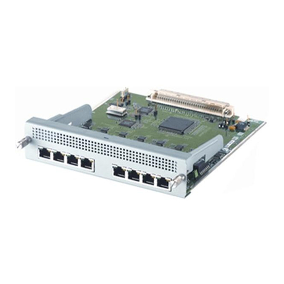
ネットワークカード Allied Telesis AT-AR042のPDF 設置および安全マニュアルをオンラインで閲覧またはダウンロードできます。Allied Telesis AT-AR042 13 ページ。 Network service module
Allied Telesis AT-AR042 にも: 設置および安全マニュアル (12 ページ)

Installation and Safety Guide
6.
Slide the NSM into place.
Slide the NSM into the NSM bay, making sure the ends of the captive screws
are aligned with the screw holes on the switch or router.
If the NSM has extractor levers, they should be in the closed position.
7.
Secure the NSM.
When the NSM has been firmly pushed into place, turn the two captive screws
to engage their threads. Tighten both captive screws at the same rate to pull
the NSM into position.
The screws will tighten when the NSM panel is in its installed position. The
captive screws should be firm but not over-tight.
If one captive screw becomes tight before the other, loosen it slightly before
proceeding.
8.
If you are not hot swapping, apply power to the switch or router.
Re-attach the power cord, and reconnect any redundant power supply. Check
that the switch or router power LED lights green.
Check the In Use LED on the switch or router rear panel. The In Use LED
lights to indicate the NSM is installed, is receiving power, and is operational.
9.
If you are hot swapping, return the NSM bay to use.
Press the recessed Hot Swap button. The Swap LED will go out and the In Use
LED will light.
If the In Use LED lights only briefly and the Swap LED then lights continuously,
the NSM is not supported by the current software release.
10. Verify the installation.
Use the show system command to verify that the switch or router has
recognised the NSM. If the NSM does not appear in the list of boards at the top
of the display, or the In Use LED fails to light, then the switch or router has not
recognised the NSM. Likely reasons are:
• Your switch or router does not support the NSM. See
and Routers" on page
• The NSM is not installed correctly. Repeat the installation process, paying
particular attention to steps 6 and 7.
If the installation still fails, see the Network Service Module Hardware Reference,
which has further troubleshooting information.
4.
"Compatible Switches
613-000610 Rev B
9
