- ページ 18
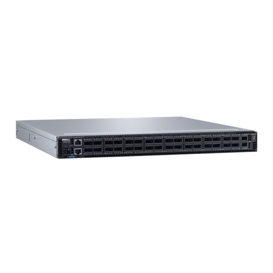
スイッチ Dell Z9100-ONのPDF インストレーション・マニュアルをオンラインで閲覧またはダウンロードできます。Dell Z9100-ON 45 ページ。 Open networking
Dell Z9100-ON にも: インストレーション・マニュアル (45 ページ), インストレーション・マニュアル (43 ページ)

To install the Z9100–ON switch, complete the installation procedures in the order described.
Always handle the Z9100–ON and its components with care. Avoid dropping the switch or its field replaceable units (FRUs).
NOTE:
ESD damage can occur if components are mishandled. Always wear an ESD-preventive wrist or heel ground strap
when handling the Z9100–ON and its components. As with all electrical devices of this type, take all the necessary safety
precautions to prevent injury when installing this switch.
NOTE:
For more information, see the Open Networking Hardware Diagnostic Guide for the Z9100–ON System.
Topics:
•
Unpack
•
Ground cable
•
Rack or cabinet installation
•
Z9100-ON switch installation
•
Optics installation
•
Port connectivity
•
Switch power up
•
After Z9100–ON installation
•
Switch replacement
Unpack
NOTE:
Before unpacking the switch, inspect the container and immediately report any evidence of damage.
When unpacking the Z9100-ON switch, ensure that the following items are included:
● One Z9100-ON switch
● One RJ-45 to DB-9 female cable
● Two sets of rail kits, no tools needed
● Two PSUs
● Five fan units
● Two country- and region-specific AC or DC power cables
● Dell Networking Getting Started Guide for the Z9100–Open Networking (ON) System
● Safety and Regulatory Information
● Warranty and Support Information
Ground cable
NOTE:
For AC-powered switches, although the third conductor of the AC power cord provides a ground path, Dell EMC
recommends grounding your switch with a dedicated ground wire.
NOTE:
For DC-powered switches, the only way to safely ground your switch is to attach a dedicated ground wire.
Depending on the type of switch, to attach a ground cable to the switch, you need one of the included M3 or M4 screws. The
switch ships with one of the following two configurations:
● One threaded hole using an included M3 screw.
● Two threaded holes using one of the two included M4 screws.
18
Z9100–ON installation
Z9100–ON installation
5
