- ページ 10
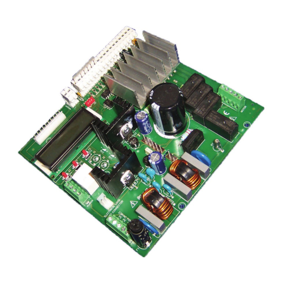
コントロールユニット Allmatic CT INVERTER AMのPDF 設置マニュアルをオンラインで閲覧またはダウンロードできます。Allmatic CT INVERTER AM 12 ページ。 Programmable control board for sliding gates with inverter technology

Pre-flashing
This function commands a blinking BEFORE each movement in order to indicate the imminent movement itself.
Zone light
There is the possibility to use the auxiliary output as a courtesy light or as a light zone (always lit-on as long as the gate is open)
Auxiliary light timeout
There is the possibility to set the delay of switching-off of the auxiliary light after the automation stops
Clock function
Input OPEN becomes input clock in case it is possible to connect a timer for the programmed opening of the automation. The contact is
understood as a command to opening and to stay open as long as this status stays closed. When the contact is opened, then the unit reset its
normal functioning, waiting for a command given by the user (if the automatic closing is required, then it must be enabled from the menu).
Water hammer in opening
If the automation is equipped with an electronic lock, then it is advisable that, when the gate is closed, the motor shortly operates in closing before
it starts the opening phase (water hammer). This function allows to unlock the electronic lock in any case, even when the weather conditions are
very bad (for example in case of ice). The activation of this function enables also the electronic lock's output.
Encoder
If the motor is equipped with a suitable encoder, then it is possible to enable the functionalities of the encoder. In such way the control board does
not work any longer "by time" but "with encoder" instead. It is possible to detect the possible blocking of the motor.
Sensor level
If it is enabled, it allows to modify the intervention sensitivity of the "stop motor" sensor. Decrease the value that is set in order to have higher
sensitivity. If the sensitivity is too high and the sensor operates without any apparent reason, then increase the value.
Sensor inversion
Allows to define the reaction of the gate in case the "stop motor" sensor applies. If the reversing is not activated, then the gate stops and waits for
a new command. If the reversing is activated, then the gate reverses shortly in case the sensor applies during the opening; it open completely in
case the sensor applies during the closing phase of the gate.
9 RESET of the control board (Menu C - Reset)
Reset of the unit according to the display indications; this reset the control board to its factory settings
WARNING: all programming and personal settings must be repeated after the reset of the control board!
10 Backlighting of the display (Menu C - Display light)
Enter MENU C and follow the instructions shown on the display in order to enable/disable the backlighting of the display itself.
The control board operates the function Energy saving which automatically switches off the display after the unit is inactive since some minutes.
The backlighting is automatically reactivated (if this function is enabled) when the user operates on the control board.
11 Housing for radio receiver
The unit disposes of a molex connector to house an ALLMATIC radio receiver. The first channel of the receiver is associated to the wired com-
mand S.S., whereas the second radio-channel (if it is present) is associated to wired command PED.
Follow the instructions of the receiver itself for learning the transmitters.
12 Auxiliary output (this output is available only with the additional card R1)
The functioning of the additional card depends on the setting of the parameter "Brake":
Parameter "Brake" OFF-1: A normally open contact is available on the output for the activation of the electronic lock. The electronic lock can be acti-
vated by previously enabling the Water Hammer in opening (parameter Water Hammer OP).
Parameter "Brake" 2-3: A contact is available on the output for the activation of an external brake.
6-1622595
rev.06
13/01/2017
Connection
with the
control unit
ITA
ENG
ELECTRICAL LOCK,
MOTOR BRAKE
FRA
ESP
DEU
POR
10 / 12
