- ページ 6
ヒーター Chromalox CXH-A/B-03SのPDF 設置、操作、メンテナンスの説明書をオンラインで閲覧またはダウンロードできます。Chromalox CXH-A/B-03S 18 ページ。 Hazardous location forced-air heater
4. Mechanical Installation
Location
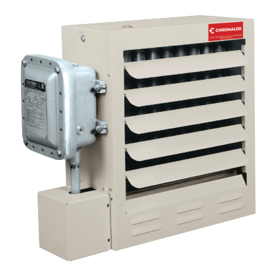
1. Model CXH-A/B heaters are certified for hazardous loca-
tions listed in table C. When un-crating confirm name-
plate (located on control enclosure lid on left side of heat-
er) matches what was ordered. If listing does not meet
hazardous location requirements, contact Chromalox im-
mediately.
2. Prior to installation ensure that heater configuration meets
environmental requirements. Model CXH-A/B heater are
designed with corrosion and moisture protection, but it is
the responsibility of the end user to ensure that materials
are compatible with the application conditions.
3. Location should be free of interference from columns,
machinery and partitions, and should allow for required
clearances (see Mounting).
4. Outlet air is hot, so avoid locations where heaters may
blow directly at personnel.
Mounting
1. Model CHX-A/B heaters are designed for use only in a
permanently mounted upright position. The maximum
out of plane dimensions as shown in Figure 2 must not be
exceeded in either direction during operation and instal-
lation. Failure to comply may cause nuisance tripping of
over-temperature cutout.
2. The ceiling or wall mounting surface and the anchoring
must be sufficient to support the combined weights of
the heater and mounting hardware (heater weights are
listed in Table A).
3. Heaters may be mounted at any convenient height above
floor. The minimum spacing shown in Figure 3 should be
maintained to adjacent walls and ceiling. If floor heat is
desired, do not mount higher than 8 to 10 feet (2.4 to 3.0
meters) above floor.
4. Controlling thermostats to individuals should be mount-
ed at shoulder height on inside walls or columns clear of
the discharge air stream of the unit. Allow at least 4 feet
(1.2m) in front of heater for air stream to discharge freely.
Do not mount mercury type thermostat directly on unit,
vibration could cause malfunction.
5. For best performance, locate heaters according to figure
1. This will promote optimal air circulation and eliminate
hot or cold spots. Heaters should blow air parallel to ex-
posed walls (do not blow directly at and should be instal
led along the windward side when installed in a building
exposed to a prevailing wind.
Figure 1 – Mounting Location
5. Heater may be mounted on a shelf or stand from the bot-
tom. Be sure that mounting clearances are maintained
and that bottom of unit has at least 1" (25mm) clearance
underneath it. This is necessary for good air circulation
and servicing of heat exchanger. All mounting methods
must allow for removal of front cover.
6. Mounting and anchoring provisions must take into ac-
count the unit vibration and cantilevered loading when
wall or pole mounted. Heater weights are listed in tables
A and B within the Specifications and Product Identifica-
tion section of the manual.
7. For proper mounting support, it is recommended that a
Chromalox supplied wall, ceiling, or pole mounting kit be
utilized.
These kits include brackets and heater installation hard-
ware. Refer to document PF458 for mounting kit installa-
tion.
8. CXH-A/B heaters are equipped with two threaded mount-
ing points (5/8-11 UNC) located on the top of the heater
case that may used to be anchor the heater to an alter-
native mounting structure using 5/8-11 (UNC) bolts and
lock-washers.
6