- ページ 34
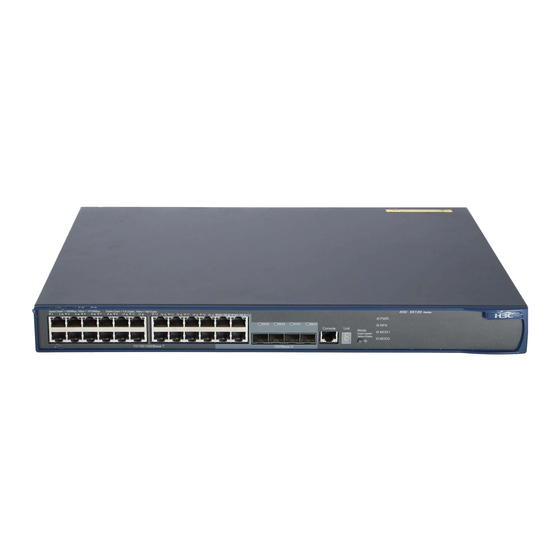
スイッチ HP 5120-24G-PoE+ EIのPDF 設定マニュアルをオンラインで閲覧またはダウンロードできます。HP 5120-24G-PoE+ EI 39 ページ。 Hp 5120 ei switch series
HP 5120-24G-PoE+ EI にも: データシート (17 ページ)

Configuration procedure
This example assumes that the system names of Device A, Device B and Device C are DeviceA, DeviceB,
and DeviceC, respectively, before the IRF fabric is formed.
Assign member IDs:
1.
# Keep the default member ID of Device A unchanged.
# Change the member ID of Device B to 2.
<DeviceB> system-view
[DeviceB] irf member 1 renumber 2
Warning: Renumbering the switch number may result in configuration change or loss.
Continue? [Y/N]:y
[DeviceB]
Power off the member devices, connect IRF links as shown in
2.
devices.
Configure IRF port bindings:
3.
# Bind Ten-GigabitEthernet 1/1/2 to IRF-port 1/2 on Device A and save the configuration.
<DeviceA> system-view
[DeviceA] interface ten-gigabitethernet 1/1/2
[DeviceA-Ten-GigabitEthernet1/1/2] shutdown
[DeviceA-Ten-GigabitEthernet1/1/2] quit
[DeviceA] irf-port 1/2
[DeviceA-irf-port1/2] port group interface ten-gigabitethernet 1/1/2
[DeviceA-irf-port1/2] quit
[DeviceA] interface ten-gigabitethernet 1/1/2
[DeviceA-Ten-GigabitEthernet1/1/2] undo shutdown
[DeviceA-Ten-GigabitEthernet1/1/2] save
# Bind Ten-GigabitEthernet 2/1/1 to IRF-port 2/1 on Device B and save the configuration.
<DeviceB> system-view
[DeviceB] interface ten-gigabitethernet 2/1/1
[DeviceB-Ten-GigabitEthernet2/1/1] shutdown
[DeviceB-Ten-GigabitEthernet2/1/1] quit
[DeviceB] irf-port 2/1
[DeviceB-irf-port2/1] port group interface ten-gigabitethernet 2/1/1
[DeviceB-irf-port2/1] quit
[DeviceB] interface ten-gigabitethernet 2/1/1
[DeviceB-Ten-GigabitEthernet2/1/1] undo shutdown
[DeviceB-Ten-GigabitEthernet2/1/1] save
# Activate IRF port configuration on Device A.
[DeviceA-Ten-GigabitEthernet1/1/2] quit
[DeviceA] irf-port-configuration active
# Activate IRF port configuration on Device B.
[DeviceB-Ten-GigabitEthernet2/1/1] quit
[DeviceB] irf-port-configuration active
After the IRF port configuration is activated, the two devices automatically elect a master. In this
example, Device A is the master. Device B automatically reboots and joins the Device A as a
subordinate switch to form an IRF fabric. The system name of the IRF fabric is DevcieA.
Configure ARP MAD:
4.
30
Figure
13, and power on the two
