- ページ 9

スイッチ HP ProCurve 1600MのPDF 計画・実施マニュアルをオンラインで閲覧またはダウンロードできます。HP ProCurve 1600M 40 ページ。 Redundant power supply
HP ProCurve 1600M にも: 仕様書 (12 ページ), リード・ミー・ファースト (8 ページ), レビュアーズ・マニュアル (27 ページ), 補足マニュアル (2 ページ), 補足マニュアル (2 ページ), インストレーション・マニュアル (28 ページ), インストレーション・マニュアル (36 ページ), インストレーション・マニュアル (28 ページ), クイック・セットアップ・マニュアル (2 ページ), クイック・セットアップ・マニュアル (4 ページ), ユーザーマニュアル (8 ページ), マニュアルの補足 (28 ページ), リード・ミー・ファースト (16 ページ), 取り付けと取り外し (2 ページ), インストレーション・マニュアル (12 ページ), 使用済み製品の分解手順 (2 ページ), インストレーション・マニュアル (46 ページ), 診断マニュアル (2 ページ), 分解手順 (2 ページ)
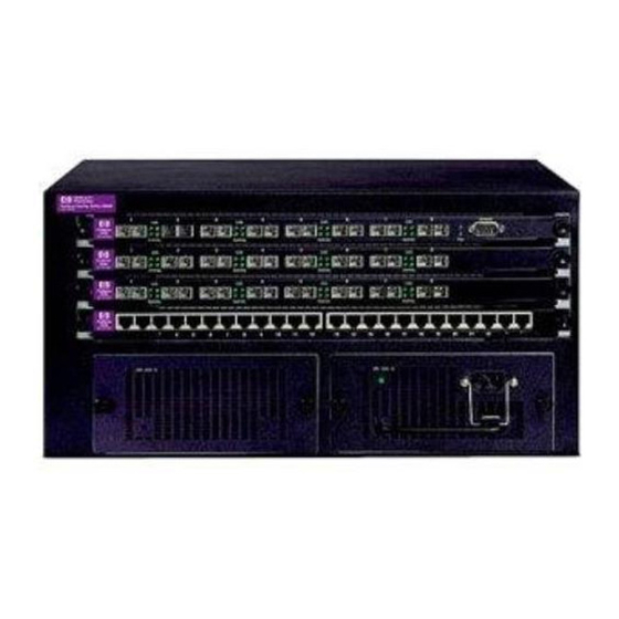
HP ProCurve 1600M 計画・実施マニュアル
The appliance can be easily moved, to wherever you can lay a LAN cable
- minimal disruption to the workplace.
Safer - no AC voltages need to be added for additional network devices.
As well as the data transfer to and from the appliance, you can use SNMP
network management infrastructure to monitor and control the
appliances.
Appliances can be shut down or reset remotely - no need for a reset button
or power switch.
When implementing wireless LAN systems it simplifies the RF survey task,
as the access point can easily be moved and wired in.

Power Through the Cable

A standard CAT5 Ethernet cable has four twisted pairs, but only two of these
pairs are used for 10Base-T and 100Base-TX data. The specification allows
two options for using these cables for power:
The spare pairs are used. The pair on pins 4 and 5 are connected
together and form the positive supply, and the pair on pins 7 and 8 are
connected and form the negative supply.
The data pairs are used. Since Ethernet pairs are transformer coupled
at each end, it is possible to apply DC power to the center tap of the
isolation transformer without upsetting the data transfer. In this mode of
operation the pair on pins 3 and 6 and the pair on pins 1 and 2 can be of
either polarity.
The standard does not allow both pairs (spare and data) to be used - a choice
must be made. The Power Sourcing Equipment (PSE) applies power to either
set of wires. Hewlett-Packard has chosen to supply PoE power over the data
pair. The Powered Device (PD) must be able to accept power from both
options.
An obvious requirement of the specification is to prevent damage to existing
Ethernet equipment. A discovery process, run from the PSE, examines the
Ethernet cables, looking for devices that comply with the specification. It does
this by applying a small current-limited voltage to the cable and checks for the
presence of a 25k ohm resistor in the remote device. Only if the resistor is
present, will the full wattage be applied, but this is still current-limited to
prevent damage to cables and equipment in fault conditions.
The Powered Device must continue to draw a minimum current. If it does not
(for example, when the device is unplugged) then the PSE removes the power
and the discovery process begins again.
Introduction
Overview
1-3