- ページ 3
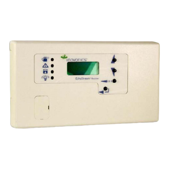
レシーバー Alpha Communications TekTone NC505ESのPDF 据付・取扱説明書をオンラインで閲覧またはダウンロードできます。Alpha Communications TekTone NC505ES 6 ページ。 Remote lcd receiver

What's in the Box
• 2 pan head screws
• 2 plastic anchors
• 2 squares of two-sided tape
• 1 two-pin jumper
• 1 OEM installation sheet
Please note: The NC505ES requires a PK505 transformer,
ordered separately. Please verify that all power supplies are
available before installation.
• Six onboard Type C relay outputs for N/O or N/C operation.
• Jam detection monitors all channels for interference.
• A reset terminal is provided in the receiver to allow external
receiver resets.
• A tamper terminal is provided in the receiver to allow external
tamper monitoring.
• Add up to 16 EchoStream transmitters.
• Two-line text display.
Chapter 2—Installation
Mounting
Use the provided anchors and screws to mount the receiver in
a location accessible for future maintenance. Caution: Mount
the receiver in a location removed from metal. Metal objects
(duct work, wire mesh screens, boxes) will reduce the reception
range.
Connections
Connect Power Cabling
Before beginning startup, connect power to the receiver:
1. Use a small screwdriver to press the three housing
release tabs on the top or bottom of the receiver and
separate the housing.
2. Connect power cabling to the Power (Vs) and GND
connections. (See Figure 2.)
3. Power source must be 11–14 VDC. Power supply must be
unswitched, uninterrupted, and regulated. Use TekTone
part number PK505.
Copyright © TekTone Sound & Signal Mfg., Inc. All Rights Reserved.
Features
Select the Frequency Band
The NC505ES Remote LCD Receiver can use a range of
radio frequencies, and must be configured for your
geographic area. To configure the receiver:
1. Place a selection jumper on the appropriate frequency
band selection pins. (See Figure 2.)
•
Leave the jumper off the pins to set the frequency
range to 902–928 MHz for North America. Note:
North America is also selected when the jumper is
attached to only one pin. This prevents the jumper
from being lost when selecting North America.
•
Place the jumper on the top two pins, marked AUS,
to set the frequency range to 915–928 MHz for
Australia.
•
Place the jumper on the bottom two pins, marked NZ,
to set the frequency range to 921–928 MHz for New
Zealand.
2. Cycle power to reset.
Connect Output and Input Cabling
Refer to Figure 2 for connection points.
1. Connect cabling to the power loss output. The optional
power loss output is a normally closed (N/C) output that
reports power loss to an external device.
2. Connect cabling to the tamper output. The optional
tamper output is a normally open (N/O) output that
reports receiver case tamper to an external device.
3. Connect cabling to the jam output. The optional jam
output is a normally closed (N/C) output that opens when
noise thresholds on all transmission channels remain
above a predetermined value for more than 20 seconds.
4. Connect cabling to the reset input. The optional reset
input circuit permits installation of a remote momentary
normally open (N/O) switch to clear faults, unlatch relay
outputs and reset the receiver to a normal state.
5. Connect cabling to the output terminals. The NC505ES
provides six Form C relay outputs.
®
6. Close the NC505ES receiver housing.
Field Wiring Examples
Figure 3 shows various uses of the relay outputs from the
NC505ES. Wire size should be no smaller than 22 gauge
and no larger than 18 gauge (due to housing space). Use 18
gauge cable to connect dome lights and the external power
supply.
IL882 NC050ES Remote LCD Receiver Manual • Page 3
