QUICK START GUIDE
QUICK START PROCEDURE
A
V
Supply
IN
<60 V
CIRCUIT PERFORMANCE
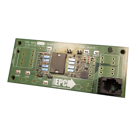
The EPC9115 demonstration circuit was designed to showcase the
size and performance that can readily be achieved using eGaN
FETs. The 300 kHz operating frequency is 50% - 100% higher than
typical commercial eighth-brick converters.
Figure 4 shows typical full-load waveforms for a 52 V input voltage
using probe tip adapters as shown in Figure 3. Figure 5 shows efficiency
plots for several input voltages at 400 LFM (2 m/s) airflow at 25 °C.
Data are taken after converter reaches thermal steady state.
EPC – EFFICIENT POWER CONVERSION CORPORATION |
Regulated Eigth-brick Demo Board
EPC 9115,
VIN−
VIN+
VIN−
Vgs
Vds
V
Primary Waveforms
Figure 2: Proper Connection and Measurement Setup
Do not use probe ground lead
Minimize loop
Figure 3: Proper Measurement of Switch Nodes or Output Voltage
WWW.EPC-CO.COM
V
Secondary Waveforms
Vds
Vgs
VOUT+
VOUT−
V
pri
Figure 4: Typical waveforms taken at 52 V
| COPYRIGHT 2015 |
V
Drain Node
sec
5 V/div
Switch Node
10 V/div
V
Gate
pri
4 V/div
to 12 V
IN
OUT
EPC9115
A
Load
/42 A
OUT
| PAGE 3