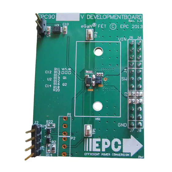
- ページ 4
マザーボード EPC EPC9030のPDF クイック・スタート・マニュアルをオンラインで閲覧またはダウンロードできます。EPC EPC9030 7 ページ。 Epc9022, half bridge with gate drive for epc8000 family

Gate Drive Supply
Gate Drive
V
DD
Regulator
LM5113
Logic and
PWM
Gate
Dead-time
Input
Driver
Adjust
Figure 1: Block Diagram of Development Board
Figure 4: Typical Waveforms for V
= 28 V to 3.3 V/4 A (5 MHz) Buck converter
IN
CH2: (V
) Switch node voltage –– CH4: V
OUT
Half-Bridge with Bypass
V
IN
OUT
Input voltage
PWM
7 V – 12 V
–
V
Supply
DD
+
Gate Drive Supply
(Note Polarity)
+
V
V
IN
–
(For E ciency
Measurement)
PWM Input
EFFICIENT POWER CONVERSION
Figure 2: Proper Connection and Measurement Setup
Figure 3: Proper Measurement of Switch Node – OUT
A
I
IN
Switch Node
V
External Circuit
EPC
Do not use probe ground lead
Do not let
probe tip
touch the
low-side die!
Minimize loop
Place probe
tip on pad
<28 V
+
Supply
IN
–
