- ページ 4
コントローラー dicodes FL80のPDF マニュアルをオンラインで閲覧またはダウンロードできます。dicodes FL80 11 ページ。 Electronic circuit board

2.2. The On-Board USB-Charger
The On-Board charging circuit is an active switch mode battery charger in contrast to the
often used linear charger on other circuits. The active charger has the main advantage that
it is much more efficient. This enables the circuit to charge with much higher currents
compared to a linear charger, and thus charging the battery faster.
The charger is compatible with the battery charging specification 1.2 (BC1.2). The
specification defines how a charging circuit should detect the supply strength of the source
connected to it. Thus the charger can detect how much current it may draw from the
source, i.e. 500mA from a PC or laptop up to 3A from a dedicated charging port.
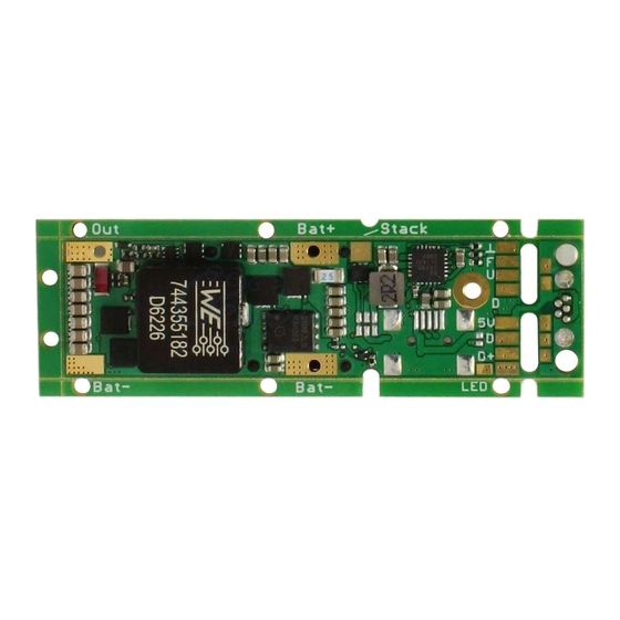
On the board there is a vertical 5pin Micro-USB-B plug on an extension board, which can
be cut off, if not used in that position. There is also the option to order the board with a
mini-USB plug populated on the bottom side (see ordering in formation).
Beside this there is an option to populate a 6pin 0.5mm pitch FPC connector on the board
and soldering pads on the bottom. The usage of this FPC connector has two options:
- When solder jumper J2 is closed, an external daughter board can be connected by the
FPC connection, carrying an USB plug, which is mounted anywhere else in the design.
- When solder jumper J3 is closed AND J1 opened, the FPC plug is connected to the battery
instead of the on-board charger.
This gives the opportunity to implement a different charger, or, when two batteries in
series are used, to charge the batteries with a charger capable to charge 2 series batteries.
When the on-board charger circuitry is used note the following behavior: As soon as the
USB-Plug is connected (with a battery connected to the board), the red LED lamp is on to
show the charging is in progress. When the battery is almost completely charged, the LED
starts blinking slowly and is off, when battery is fully charged.
By plugging in the USB-cable, the processor is switched on as well. Note that the processor
will not react to any buttons, if it was actively switched off before the USB-cable was
attached or when it was actively switched off while the USB cable is attached.
It can only be switched on again by removing the USB-connection and pressing the fire
button five times in this case.
If it was NOT switched off actively by the user, but because of auto-power-off, the buttons
will react normal.
It is also possible to vape during the charging, although this is not recommended because
the charging circuit performs the charging in different steps, which depend on the battery
voltage. By vaping during charging, the voltage drop in the battery can let the charger
switch between phases and reset certain safety timers. Normally this is not critical, but
with defective or bad batteries, the safety timers will not work properly in this case.
