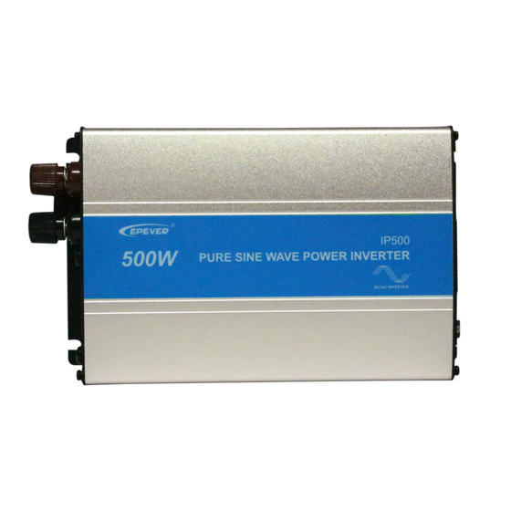
インバーター Epever IP500-21のPDF マニュアルをオンラインで閲覧またはダウンロードできます。Epever IP500-21 2 ページ。

※Thank you for selecting the IPower series Pure Sine Wave Inverter.
Please read this manual carefully before using the product and pay
attention to the safety information.
IPower series Pure Sine Wave Inverter
1. Overview
IPower series is a pure sine wave inverter which can convert 12/24Vdc into
110/120Vac. It has the characteristics of concise outline, compact size, high
reliability, high efficiency, easy to install and operate and so on. The inverter
applicable to household emergency lighting system, vehicle mounted
system and small field power supply, etc.
Features:
Complete isolation-type inverter technology
Adoption of advanced SPWM technology, pure sine wave output
Low output harmonic distortion (THD≤5%)
Optional output voltage and frequency at 110/120Vac,50/60Hz
High conversion efficiency up to 91%
USB output 5Vdc/1A
Extensive Electronic protection
2. Product Features
Figure1 DC Input panel
Figure2 Output panel
①
DC positive input
②
Fuse
③
Fan Ventilation
④
DC negative input
⑤
AC output switch
NOTE:12V system input voltage range is 10.8~16V; 24V
system input voltage range is 21.6~32V.
BEIJING EPSOLAR TECHNOLOGY CO., LTD.
⑥
Fault indicator(red)
⑦
Working indicator(green)
⑧
USB output interface (5VDC/1A)
⑨
AC Outlet
⑩
Mode switch
1
Tel:+86-10-82894112 / 82894962 Website:www.epsolarpv.com/www.epever.com
1) Fan Ventilation
When the heat sink temperature is more than 40℃ or internal temperature
is more than 45℃, the fan will turn on automatically.
When the heat sink temperature is lower than 35℃ and internal
temperature is lower than 40℃, the fan will turn off automatically.
2) Mode Switch
The output mode can be changed by the mode switch. This mode can be
switched online.
When the switch No.1 is on the ON side, output frequency is 60Hz,
otherwise is 50Hz.
When the switch No.2 is on the ON side, the output voltage is 120Vac,
otherwise is 110Vac.
NOTE: Both the output frequency and the output voltage
change availability after restart the inverter.
WARNING:DO NOT turn ON/OFF the mode switch when the
inverter is working.
3) LED indicator and Buzzer
Working indicator
Fault indicator
Green On Solid
Red OFF
Green Slowly
Red OFF
Flashing
Green Fast
Red OFF
Flashing
Green On Solid
Red On Solid
Red Fast
Green OFF
Flashing
Red Slowly
Green On Solid
Flashing
Green OFF
Red OFF
4) AC Outlet (optional)
Universal:
Australia/New Zealand:
European:
3. Installation and wiring
1)Notes of installation
Do not expose the inverter to humid, flammable, explosive or dust
environment.
Please make sure the air ventilation clearance around the inverter is
more than 10cm.
Never install the inverter in a sealed enclosure with flooded batteries.
Buzzer
Status
No Sounding
Output is ON
Sounding
Input low voltage
Sounding
Input over voltage
Sounding
Over temperature
Sounding
Load short circuit
Sounding
Overload
Output voltage
Sounding
abnormal
2
