アダプター Epever WiFi 2.4G DB9 BのPDF クイック・スタート・マニュアルをオンラインで閲覧またはダウンロードできます。Epever WiFi 2.4G DB9 B 2 ページ。 Wifi 2.4g adapter
Epever WiFi 2.4G DB9 B にも: クイック・スタート・マニュアル (2 ページ)
HUIZHOU EPEVER TECHNOLOGY CO., LTD.
※ Thanks for selecting the EPEVER WiFi transmission terminal;
please read this manual carefully before using the product.
※ Please keep this manual for future reference.
WiFi 2.4G Adapter
1. Overview
Through a local WiFi 2.4G network, the WiFi 2.4G adapter can transmit all
operational data from the EPEVER solar controller,
inverter/charger to the EPEVER cloud server in real-time. Users can
remotely monitor the connected devices and program parameters via the
EPEVER server, mobile APP, or the large screen.
Features:
Applicable to EPEVER controllers, inverters, or inverter/charger with RJ45,
DB9 interfaces
Use immediately after connecting, easy and convenient operation
Directly powered by the communication port
Up to 30 meters communication distance
Support the "Local" and "EPEVER Cloud" working mode.
One key to restore the factory settings
2. Appearance
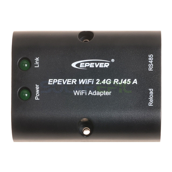
2.1 EPEVER WiFi 2.4G RJ45 A
Interface instruction
No.
Name
Connect to the solar controller, inverter, or
❶
RJ45 port
inverter/charger
One key to restore factory settings
Note: Long press the Reload button with a
❷
sharp object when the terminal's power is on.
Reload button
The Link indicator flashes twice quickly, and the
factory settings are restored successfully.
❸
Link indicator
Indicate the communication status
❹
Power indicator
Indicate the power status
Indicator instruction
Indicator
Status
ON solid in green
Link indicator
OFF
Fast flashing in green
ON solid in green
Power indicator
OFF
2.2 EPEVER WiFi 2.4G DB9 B
Interface instruction
EPEVER WiFi 2.4G RJ45 A
EPEVER WiFi 2.4G DB9 B
inverter,
Instruction
Instruction
Connect to the WiFi
Not connect to the WiFi
Reset to the factory mode
Normal powered on
Not powered on
1
Tel:+86-10-82894896/82894112/+86-752-3889706
No.
Name
DB9 male
❶
connector
❷
Antenna
❸
Reset button
❹
Network Indicator
or
❺
Power Indicator
Connect the EPEVER WiFi 2.4G DB9 B to the solar controller, inverter, or
inverter/charger by a DB-9 female connector. The wire sequence and name
of the DB9 female connector are shown below.
No.
Name
Instruction
1
NC
Floating
2
NC
Floating
Power2
3
VCC2
(12V/200mA)
4
GND2
Power GND2
5
GND1
Power GND1
Indicator instruction
Indicator
ON solid in green
Network Indicator
ON solid in green
Power Indicator
3. System connection
Step1: Connect the WiFi transmission terminal to the controller, inverter, or
inverter/charger through the RJ45 port or the DB9 connector. Take the
connection diagram of the inverter/charger as an example as follows:
Note: EPEVER WiFi 2.4G RJ45 A is suitable for the controller, inverter, or
inverter/charger designed with an RJ45 port. EPEVER WiFi 2.4G DB9 B is ideal for
the device designed with a DB9 interface. For detailed connection cables, refer to
the connected device's accessories list.
Website:www.epever.com
Instruction
Connect to the solar controller, inverter, or
inverter/charger
Enhance the signal transmission
One key to restore factory settings
Note: Long press the Reset button through the
KEY hole with a sharp object when the
terminal's power is on. The indicator light
flashes twice quickly, and the factory settings
are restored.
Indicate the communication status(Observe
the indicator status through the KEY hole)
Indicate the power status
No.
Name
6
NC
7
RS485-A
8
RS485-B
9
VCC1
Status
Instruction
Connect to the WiFi
OFF
Not connect to the WiFi
Fast flashing in
Reset to the factory mode
green
Normal powered on
OFF
Not powered on
2
Instruction
Floating
RS485-A
RS485-B
Power1
(5V/400mA)