- ページ 10
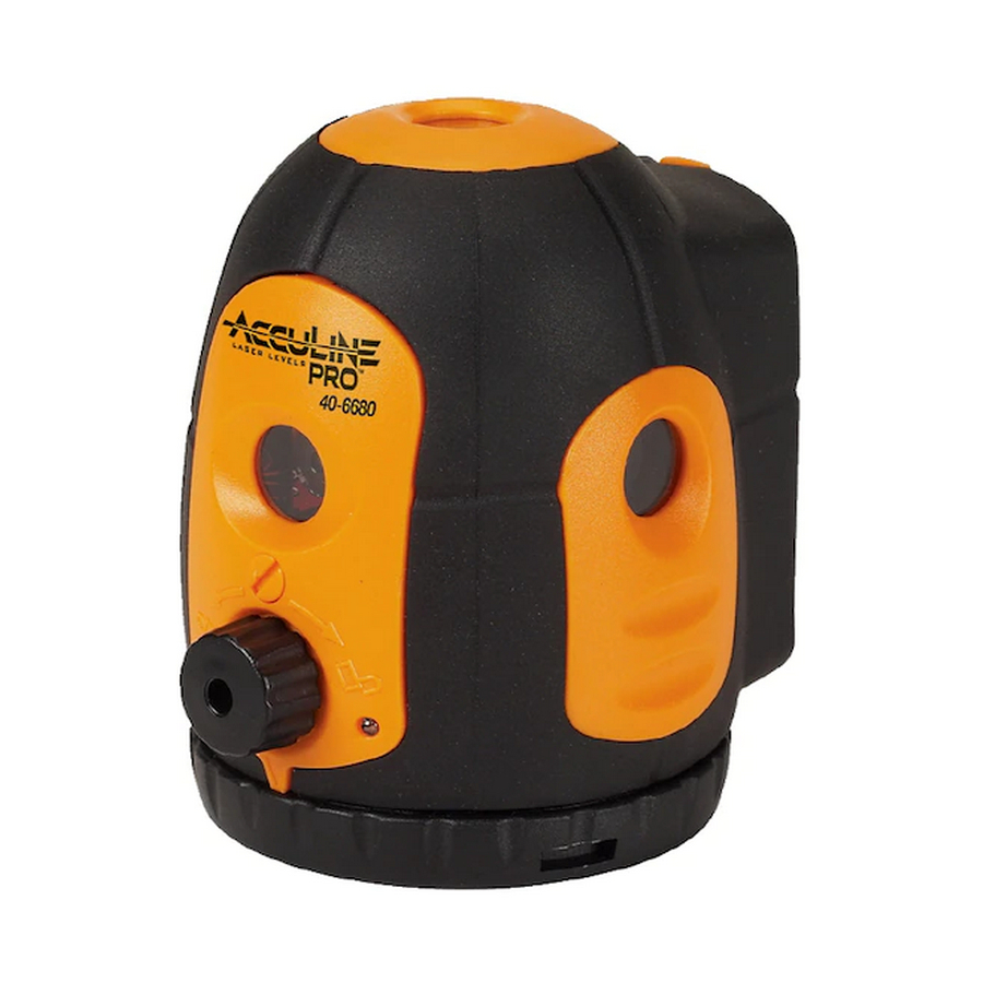
レーザーレベル AccuLine 40-6680のPDF サービスマニュアルをオンラインで閲覧またはダウンロードできます。AccuLine 40-6680 16 ページ。 5 beam laser pointer
AccuLine 40-6680 にも: 取扱説明書 (13 ページ)

1.
Using a Phillips screwdriver, remove 2 cross-slot plate screws M2×4(3-2), then remove the top cover module (3-1)
2.
Using a Phillips screwdriver, remove 2 cross-slot plate screws M2×4(3-6) , then remove the front cover module (3-4#)
3.
Remove out indicator light (3-5)
4.
Remove the plastic screw (3-3)
5.
Using a Phillips screwdriver, remove 2 cross-slot sunk screws M2×4(3-8), then remove the right cover module (3-7).
6.
Using a Phillips screwdriver, remove 2 cross-slot sunk screw M2×4(3-10), then remove the left cover module (3-9).
7.
Using a Phillips screwdriver, remove 4 cross-slot plate tapping screws ST2.2×6.5(3-11), then remove battery case
(3-13).
8.
Remove the piece fixing the lead (3-12)
9.
Remove the body housing(3-16)
10. Remove the left shell (3-14) and right shell (3-15)
3.0 Schematic Diagram
The schematic diagram shows function blocks and general wire connections. It does not detail operation of
each functional block.
Power Switch
Prepared By: Tim Wojo
Hair Spring Modules
Main PCB
Revision - Date: 0 – 20080430
40-6680 Service Manual
Laser Modules
Alarm/Buzzer
Page 10 of 16
